Bicycle crank arm assembly

A bicycle and crank arm technology, applied in the field of bicycle crank arm components, can solve problems such as inaccuracy

Inactive Publication Date: 2007-11-07
CAMPAGNOLO SRL
View PDF1 Cites 1 Cited by
  • Summary
  • Abstract
  • Description
  • Claims
  • Application Information

AI Technical Summary

Problems solved by technology

During the insertion step, the crank arm is guided by a very short section and can travel in a direction

Method used


Image

  • Bicycle crank arm assembly
  • Bicycle crank arm assembly
  • Bicycle crank arm assembly

Examples


Embodiment Construction

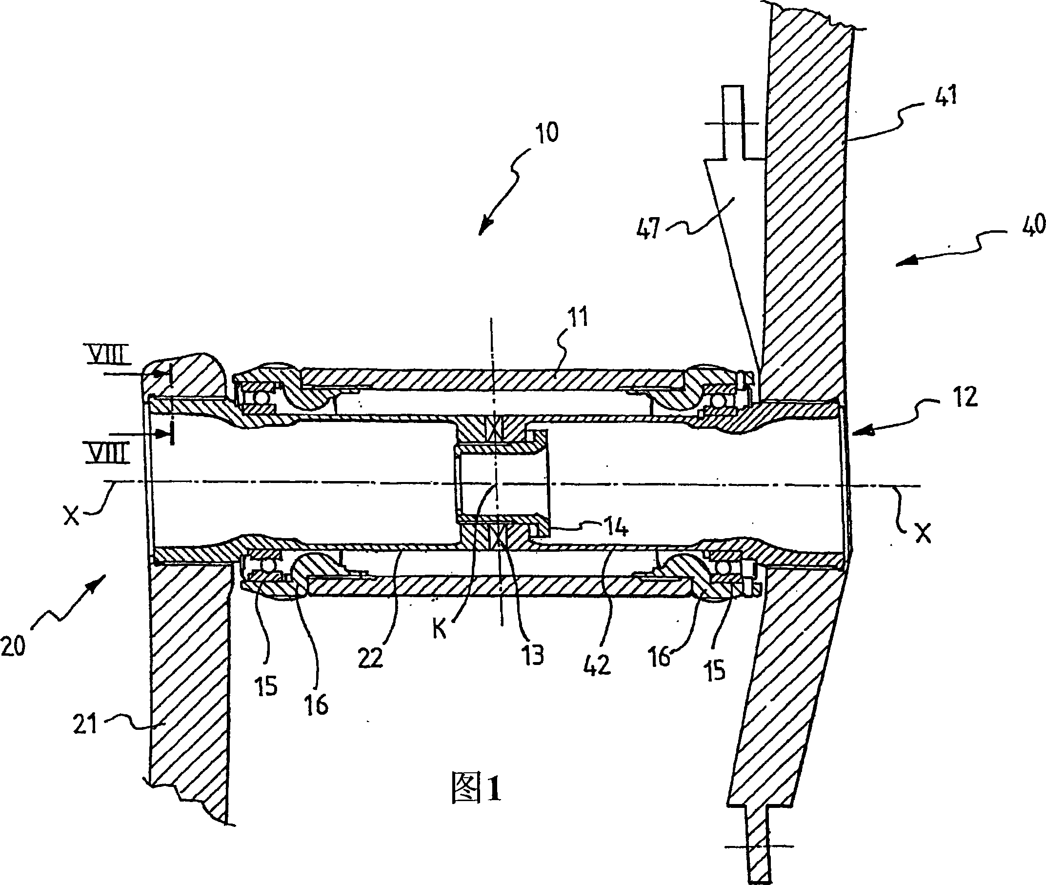
[0035] In the figures, the bottom bracket assembly of the bicycle transmission is generally indicated by 10; only the frame box 11 of the bicycle supporting the bottom bracket assembly 10 is shown.

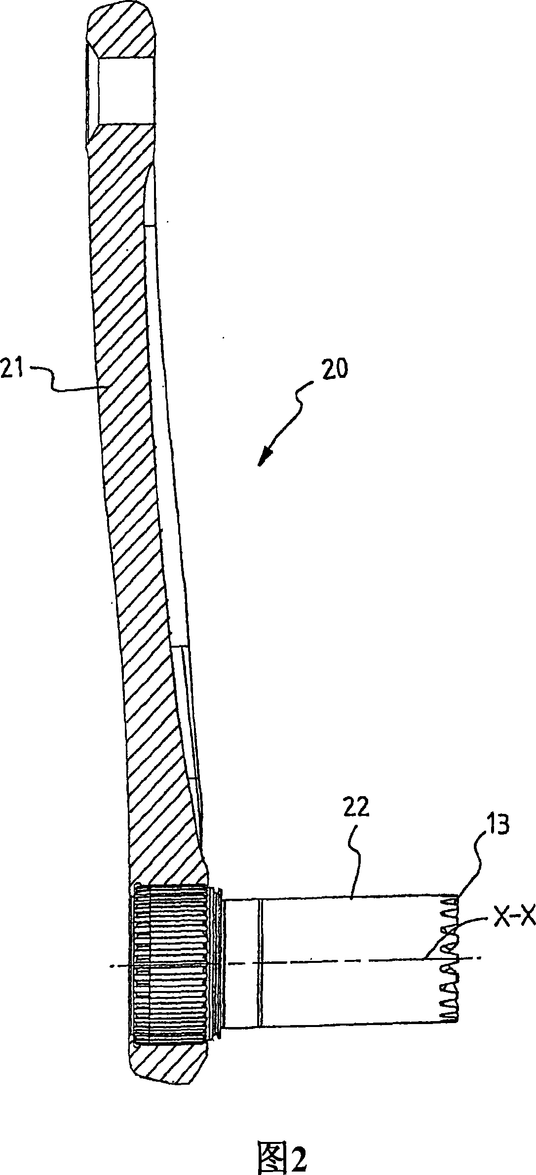
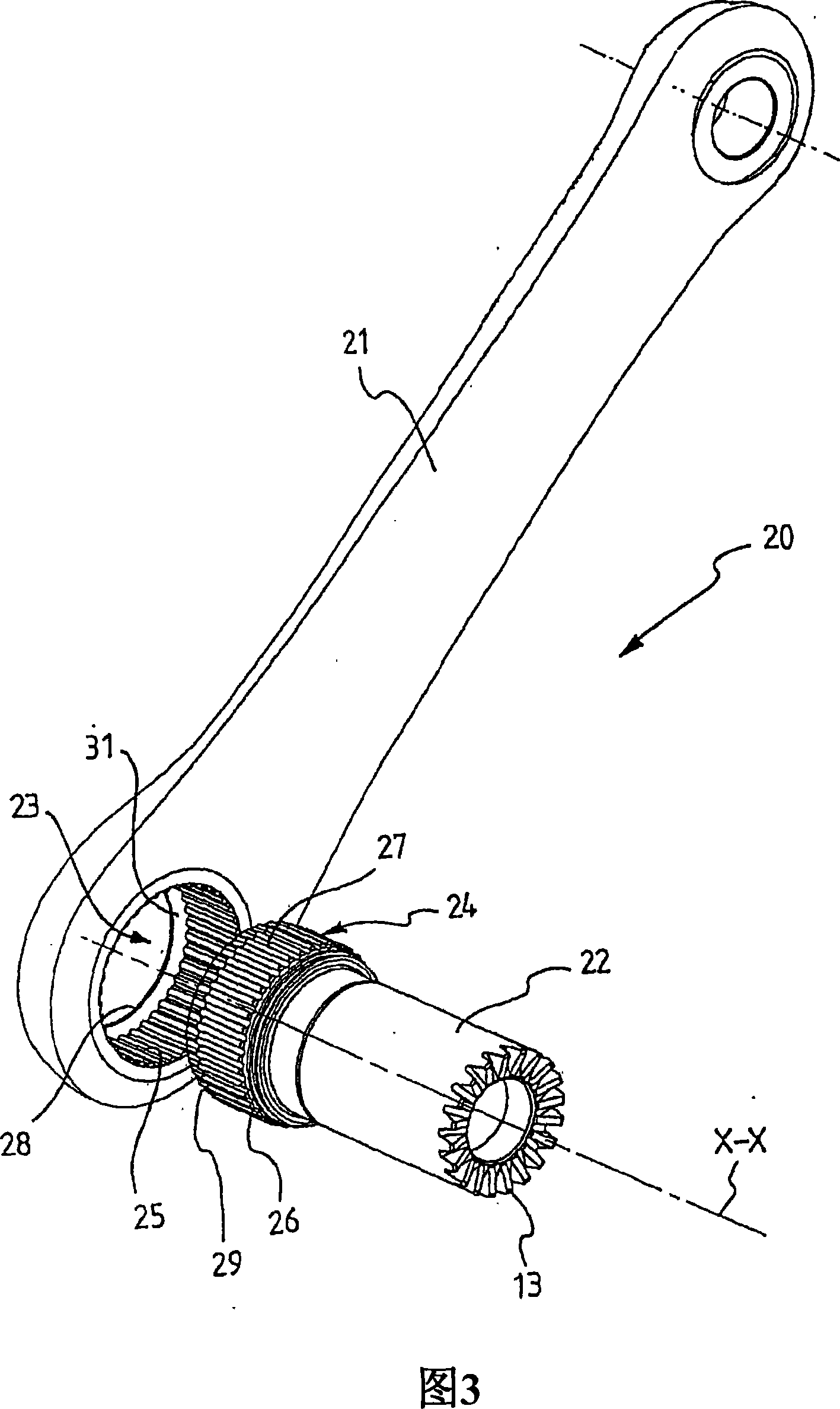
[0036] With particular reference to FIG. 1 , bottom bracket assembly 10 includes two crank arm assemblies 20 and 40 , left and right, each of which includes crank arms 21 and 41 and shaft portions 22 and 42 , respectively. The two shaft parts 22 and 42 are substantially identical to each other and rotate integrally by coupling with the front teeth 13 and the lock nut 14, which are only diagrammatically shown because they are conventional in nature, thus In use a shaft assembly, indicated generally at 12, is formed. It should be noted that in other embodiments (not shown) two different shaft parts may be provided and that one of the two parts may even be omitted, while the other may comprise the entire shaft.

[0037] The right crank assembly 40 differs from the left crank assembl...


PUM


Abstract

A bicycle crank arm assembly is provided having at least one axle portion, a crank arm mounted on the at least one axle portion, the crank arm having a coupling seat and the axle portion a coupling portion coupled to the coupling seat, the coupling seat and the coupling portion being shaped so as to make a shape coupling to ensure that the crank arm can transmit a torque to the axle portion. Between the crank arm and the axle portion adhesive material is applied. The shape coupling ensures that the crank arm and the axle portion are integral in rotation, whereas the gluing ensures the sealing of the coupling area against corrosion phenomena. The gluing also ensures a predetermined minimum force limit necessary to disassemble the crank arm assembly. The crank arm assembly has a low overall weight, a simple assembly process, and a suitable resistance to disassembling.

Description

technical field [0001] The present invention relates to a bicycle crank assembly, ie a component assembly of a bottom bracket assembly of a bicycle transmission, comprising a crank arm and at least one central shaft portion on which the crank arm is mounted. The invention also relates to a method for assembling such an assembly. Background technique [0002] With respect to the central shaft and crank arm of a bicycle transmission, "coupling" refers to the mechanical interaction between the shaft and the crank arm that forms two elements that rotate integrally about the axis of the bottom bracket assembly to allow movement between the crank arm Torque is transmitted between the shaft and the shaft. In the same context, on the other hand, "coupling" refers to the mutual mechanical action that causes the two elements to translate integrally along the axis of the bottom bracket assembly to prevent the crank arm from slipping out and thus terminate the coupling. [0003] In th...

Claims


Application Information

Patent Timeline
IPC IPC(8): B62M3/00B62M1/36
CPCB62M3/003B62M3/00
Inventor 马里奥·梅焦兰
Owner CAMPAGNOLO SRL
Why Eureka
Try Eureka