Clamping strap upward and downward turning over nail nipper

A technology of nail clippers and pressure plates, applied in the field of nail clippers, can solve the problems of affecting the life of the clipper head, unhooking, and the width of the jaws cannot be too large, and achieve the effect of improving the connection mode, rational structure, and liberating limitations

Inactive Publication Date: 2007-11-28
梁崇辉
View PDF0 Cites 0 Cited by
  • Summary
  • Abstract
  • Description
  • Claims
  • Application Information

AI Technical Summary

Problems solved by technology

This type of nail clipper has a simple structure and is widely used, but its disadvantages are also obvious. Since the pressure plate is buckled into the barb of the pin, it is inevitable that the hook will be unhooked. If the working hole is processed too large, the pressure plate will be embedded. The phenomenon of the working hole affects the normal work. Another big disadvantage of this type of nail clipper is that the width of the jaws cannot be too large. This is because the distance that the jaws can move depends on the bending degree of the pressure plate and the design of the folding point position. Based on design restrictions and ease of use, the width of the jaws generally does not exceed 3mm
At present, there is also a kind of ultra-thin nail clippers on the market. It adopts a connection structure similar to scissors. The operation part of the nail clipper, when the nail clipper is in the closed state, the volume is very small, which is mainly reflected in the thickness, and it is easy to carry, but it also has a big disadvantage. , The lower blades are forcibly squeezed together to achieve the purpose of folding, which seriously affects the life of the pliers

Method used


Image

  • Clamping strap upward and downward turning over nail nipper
  • Clamping strap upward and downward turning over nail nipper
  • Clamping strap upward and downward turning over nail nipper

Examples


Embodiment Construction

[0022] The present invention will be described in further detail below in conjunction with the accompanying drawings.

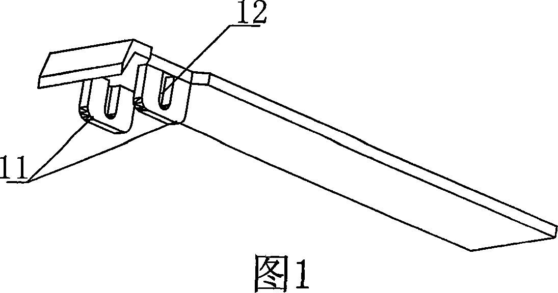
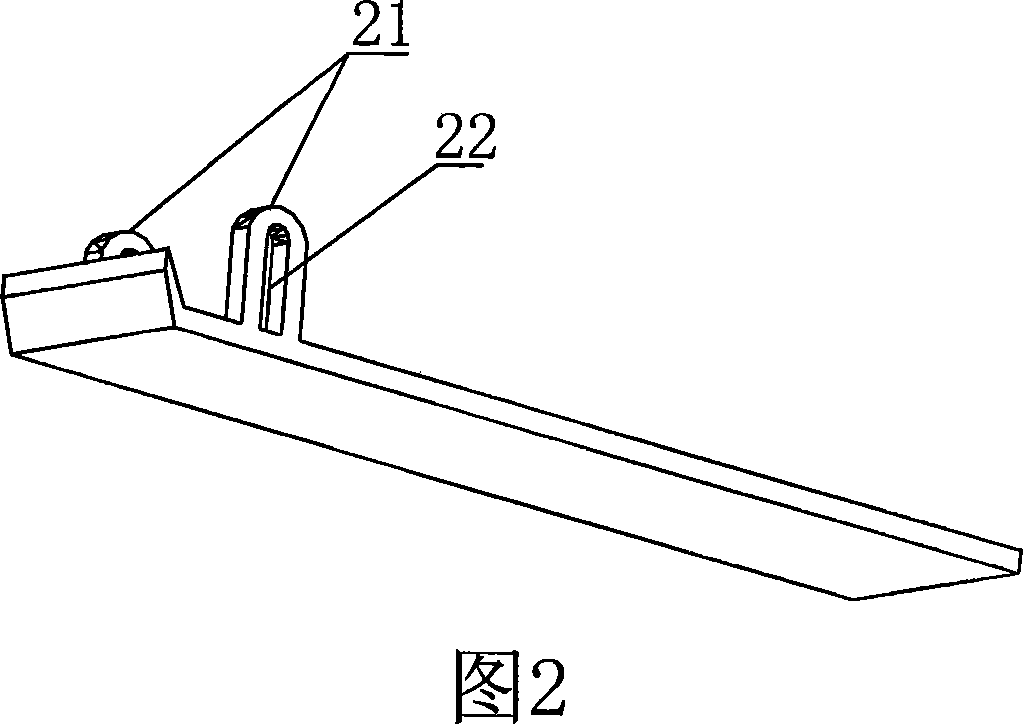
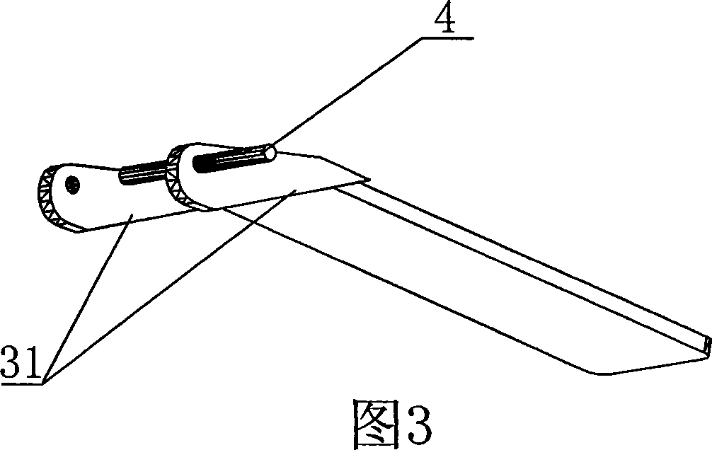
[0023] As shown in Fig. 6, Fig. 7 or Fig. 8, the present invention is a nail clipper with a pressing plate turned up and down, including an upper piece 1, a lower piece 2 and a pressing plate 3, and the tails of the upper piece 1 and the lower piece 2 are integrally formed or welded Together, the head is provided with a cutting edge, and the two sides of the head of the upper piece 1 and the lower piece 2 are respectively provided with an upper lug 11 and a lower lug 21, and a chute is arranged in the upper and lower lugs, so The intersection of the chute of the upper lug 11 and the lower lug 21 is connected by a pin 4 , the end of the pin 4 passes through the chute and extends out of the chute, and one end of the pressure plate 3 is connected with both ends of the pin 4 .

[0024] As shown in Fig. 1, Fig. 2, Fig. 4 and Fig. 5, in order to stagger the relativ...


PUM


Abstract

The present invention discloses one kind of nail clippers with transversely set pin and turnable pressing sheet. The nail clippers includes one upper sheet, one lower sheet and one pressing sheet with connected tails, edged heads, lugs and slots, and one pin for connecting the lugs and with ends extending beyond the slots and connected to one end of the pressing sheet. The present invention has reasonable structure, convenient use and small thickness.

Description

technical field [0001] The invention relates to a nail clipper, in particular to a flip-up nail clipper with a pressing plate arranged horizontally with pins. Background technique [0002] The structure of traditional nail clippers generally includes an upper piece, a lower piece, and a pressure plate. The tails of the upper piece and the lower piece are welded together, and the head is provided with a working hole. tick. This type of nail clipper has a simple structure and is widely used, but its disadvantages are also obvious. Since the pressure plate is buckled into the barb of the pin, it is inevitable that the hook will be unhooked. If the working hole is processed too large, the pressure plate will be embedded. The phenomenon of the working hole affects the normal work. Another big disadvantage of this type of nail clipper is that the width of the jaws cannot be too large. This is because the distance that the jaws can move depends on the bending degree of the pressur...

Claims


Application Information

Patent Timeline
Patent Type & Authority Applications(China)
IPC IPC(8): A45D29/02
Inventor 梁崇辉
Owner 梁崇辉
Why Eureka
Try Eureka