Clamping strap upward and downward turning over nail nipper

A technology of nail clippers and pressure plates, applied in the field of nail clippers, can solve problems such as the width of the jaws cannot be too large, affect normal work, and decoupling, and achieve the effects of easy nail removal, liberation of limitations, and improved connection methods

Inactive Publication Date: 2008-01-09
梁崇辉
View PDF0 Cites 0 Cited by
  • Summary
  • Abstract
  • Description
  • Claims
  • Application Information

AI Technical Summary

Problems solved by technology

This type of nail clipper has a simple structure and is widely used, but its disadvantages are also obvious. Since the pressure plate is buckled into the barb of the pin, it is inevitable that the hook will be unhooked. If the working hole is processed too large, the pressure plate will be embedded. The phenomenon of the working hole affects the normal work. Another big disadvantage of this type of nail clipper is that the width of the jaws cannot be too large. Based on design restrictions and ease of use, the width of the jaws generally does not exceed 3mm

Method used


Image

  • Clamping strap upward and downward turning over nail nipper
  • Clamping strap upward and downward turning over nail nipper

Examples


Embodiment Construction

[0017] The present invention will be described in further detail below in conjunction with the accompanying drawings.

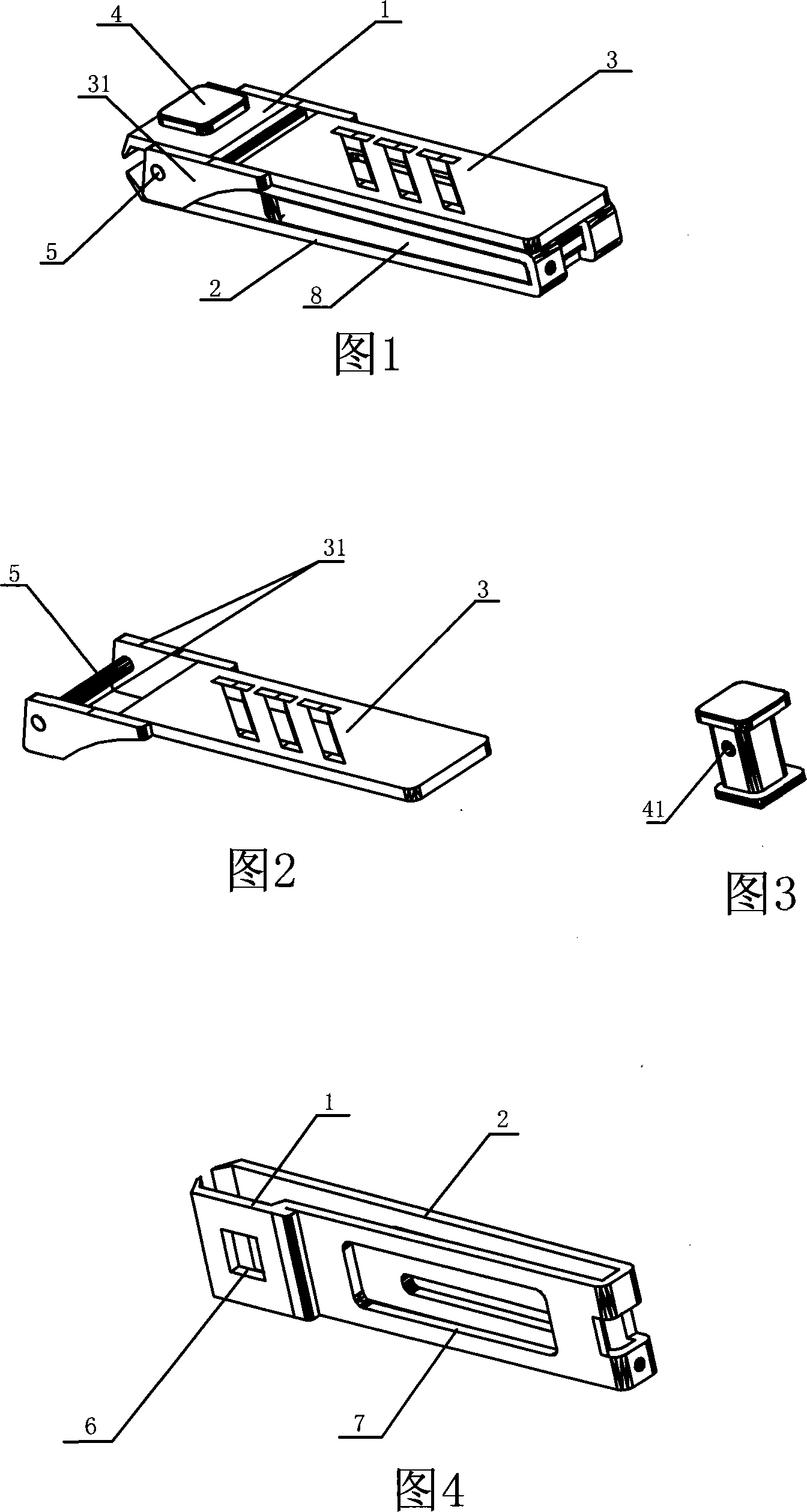
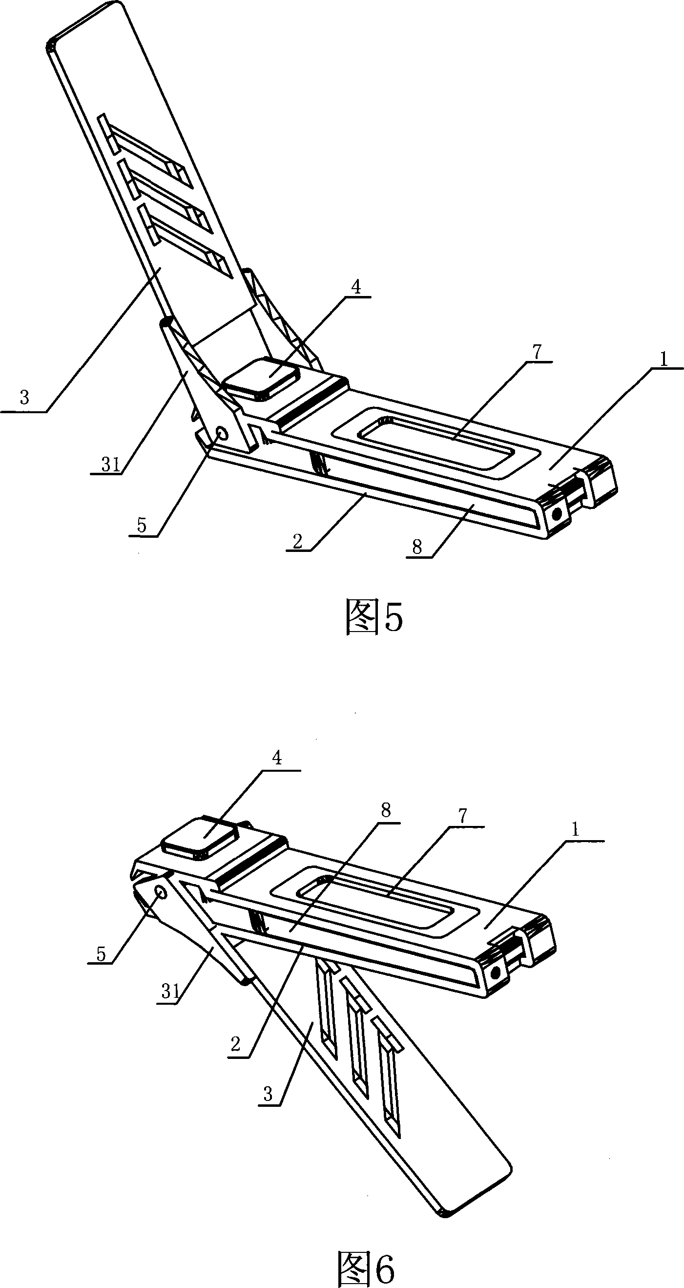
[0018] As shown in Fig. 1 and Fig. 3, the present invention is a nail clipper with a pressing plate turned up and down, comprising an upper piece 1, a lower piece 2 and a pressing plate 3, the tails of the upper piece 1 and the lower piece 2 are integrally formed or welded together, and the head A working hole 6 is provided, and a pin 4 is perforated in the working hole 6, and one end of the pressing plate 3 is connected with one end of the pin 4, and the diameter of both ends of the pin 4 is larger than that of the nail shaft part and the working hole 6, and the pin 4 is in the shape of a "working hole". "type structure, the heads of the upper piece 1 and the lower piece 2 are installed between the two ends of the pin 6, a through hole 41 is provided on the nail shaft between the heads of the upper piece 1 and the lower piece 2, and one end of the pressure pl...


PUM


Abstract

The present invention discloses a nail clippers whose pressure plate can be upward and downward turned. It includes an upper plate, a lower plate and a pressure plate. The tail portions of said upper plate and lower plate are integrally formed or welded together, the head portions of said upper plate and lower plate are respectively equipped with a working hole, in said working hole a pin bolt is set, one end of said pressure plate is connected with one end of said pin bolt, and said pin bolt is made into the 'I'-shaped structure, the head portions of upper plate and lower plate are mounted between two ends of said pin bolt, on the pin shaft between upper plate head portion and lower plate head portion a through hole is set, one end of said pressure plate is fastened into said through hole and connected with said pin bolt.

Description

technical field [0001] The present invention relates to a kind of nail clipper, more specifically, relates to a kind of nail clipper with pressing plate turned up and down. Background technique [0002] The structure of traditional nail clippers generally includes an upper piece, a lower piece, and a pressure plate. The tails of the upper piece and the lower piece are welded together, and the head is provided with a working hole. tick. This type of nail clipper has a simple structure and is widely used, but its disadvantages are also obvious. Since the pressure plate is buckled into the barb of the pin, it is inevitable that the hook will be unhooked. If the working hole is processed too large, the pressure plate will be embedded. The phenomenon of the working hole affects the normal work. Another big disadvantage of this type of nail clipper is that the width of the jaws cannot be too large. Based on design limitations and ease of use, the width of the jaws generally does...

Claims


Application Information

Patent Timeline
Patent Type & Authority Applications(China)
IPC IPC(8): A45D29/02
Inventor 梁崇辉
Owner 梁崇辉
Why Eureka
Try Eureka