Aquaculture feeding system

An aquaculture and feeder technology, applied in fish farming, application, animal husbandry, etc., can solve the problems of feeder failure, inability to work, damage and crushing of feed particles, etc., to achieve strong adaptability, uniform feeding, and consumption. small effect

Inactive Publication Date: 2013-05-01
ZHEJIANG MARINE DEV RES INST
View PDF10 Cites 17 Cited by
  • Summary
  • Abstract
  • Description
  • Claims
  • Application Information

AI Technical Summary

Problems solved by technology

[0003] The first purpose of the present invention is to overcome the problem that the feed particles will be destroyed and pulverized in the process of throwing the feed in the existing aquaculture feeder, and become dust and scatter, resulting in waste of feed, and to provide a feeder with low energy consumption and low cost. It is an aquaculture feeding system that is low in weight, uniform in feeding, and can effectively solve

Method used


Image

  • Aquaculture feeding system
  • Aquaculture feeding system
  • Aquaculture feeding system

Examples


Embodiment Construction

[0023] Below in conjunction with accompanying drawing and specific embodiment the present invention is described in further detail:

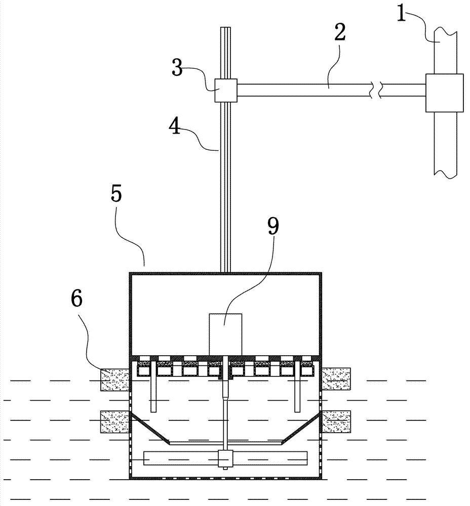
[0024] Such as figure 1 As shown, an aquaculture feeding system includes a column 1, a turnover rod 2 that can rotate around the column, a feed box 5 and a floating block 6 arranged on the outer surface of the feed box. Turnover bar 2 ends are provided with vertical guide sleeve 3, and the inwall of vertical guide sleeve is provided with vertical guide groove. A second vertical guide rod 4 is provided on the top surface of the material box 5, and a vertical guide block extending from the bottom of the second vertical guide rod to the top is provided on the side of the second vertical guide rod. The second vertical guide rod 4 can slide up and down and is arranged in the vertical guide sleeve 3, and the vertical guide block is arranged in the vertical guide groove.

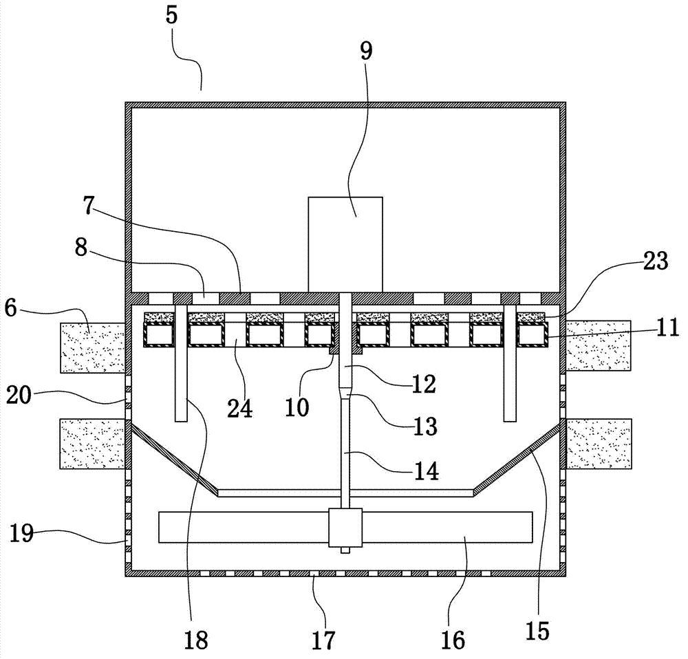
[0025] Such as figure 1 , figure 2As shown, the cross section of the feed b...


PUM


Abstract

The invention discloses an aquaculture feeding system and aims at providing the feeding system capable of effectively solving the problems that feed wastage is caused during feeding of a feeder and the feeder cannot work normally when the feed is damped. The aquaculture feeding system comprises a feed box. An isolating layer is arranged below the top surface of the chamber body of the feed box. A first vertical guide rod is arranged on the lower surface of the isolating layer. A baffle which can move along the first vertical guide rod is arranged below the isolating layer. The buoyancy force of the baffle is larger than gravity force. A plurality of upper discharge holes are arranged on the isolating layer. A plurality of lower discharge holes are arranged on the baffle. The upper discharge holes and the lower discharge holes are distributed in a staggered way. A motor is arranged at the middle part of the upper surface of the isolating layer. A vertical screw is arranged in the chamber body of the feed box. The vertical screw penetrates through the baffle and the isolating layer and is connected with the rotor of the motor. A nut is arranged at the middle part of the baffle and is sheathed on the vertical screw. A coaxial polished rod is arranged at the lower end of the vertical screw. An impeller is arranged at the lower part of the polished rod. A plurality of discharge holes are arranged on the side surface of the feed box relative to the impeller.

Description

technical field [0001] The invention relates to the field of aquaculture, in particular to an aquaculture feeding system. Background technique [0002] With the development of the aquaculture industry, various feeders have been used in the aquaculture industry. The current aquaculture feeder is usually set above the water surface. The feeder drives the static feed particles through mechanical power, so that the feed particles obtain a higher speed instantly, and then throw them out from the outlet of the feeder and fall into the water. For example, Chinese Patent Publication No. CN201430844, the publication date was March 31, 2010, and the name of the invention is the angle feeding machine. The application discloses a angle feeding machine. The motor has an impeller fixed on the shaft end of the motor, and a convex ring and an impeller feeding port are arranged on the upper middle part of the impeller; the feeding port of the feeding pipe is arranged on the feeding hole on ...

Claims


Application Information

Patent Timeline
IPC IPC(8): A01K61/02
Inventor 杨会成周秀锦周宇芳郑斌廖妙飞付万冬陈孟相瑜
Owner ZHEJIANG MARINE DEV RES INST
Why Eureka
Try Eureka