Optical disk apparatus

An optical disc device and optical disc technology, applied in packaging, head configuration/installation, optical recording/reproduction, etc., can solve problems such as the gap between the objective lens and the turntable

Inactive Publication Date: 2007-12-12
SANYO ELECTRIC CO LTD +1
View PDF0 Cites 0 Cited by
  • Summary
  • Abstract
  • Description
  • Claims
  • Application Information

AI Technical Summary

Problems solved by technology

Therefore, in the case of arranging two objective lenses side by side in the radial direction of the optical disc, there will be a gap between the objective lens on the inner peripheral side of the optical disc and the turntable.

Method used


Image

  • Optical disk apparatus
  • Optical disk apparatus
  • Optical disk apparatus

Examples


Embodiment 1

[0038] In this embodiment, the present invention is applied to an optical disc device for recording and reproducing next-generation DVDs and CDs.

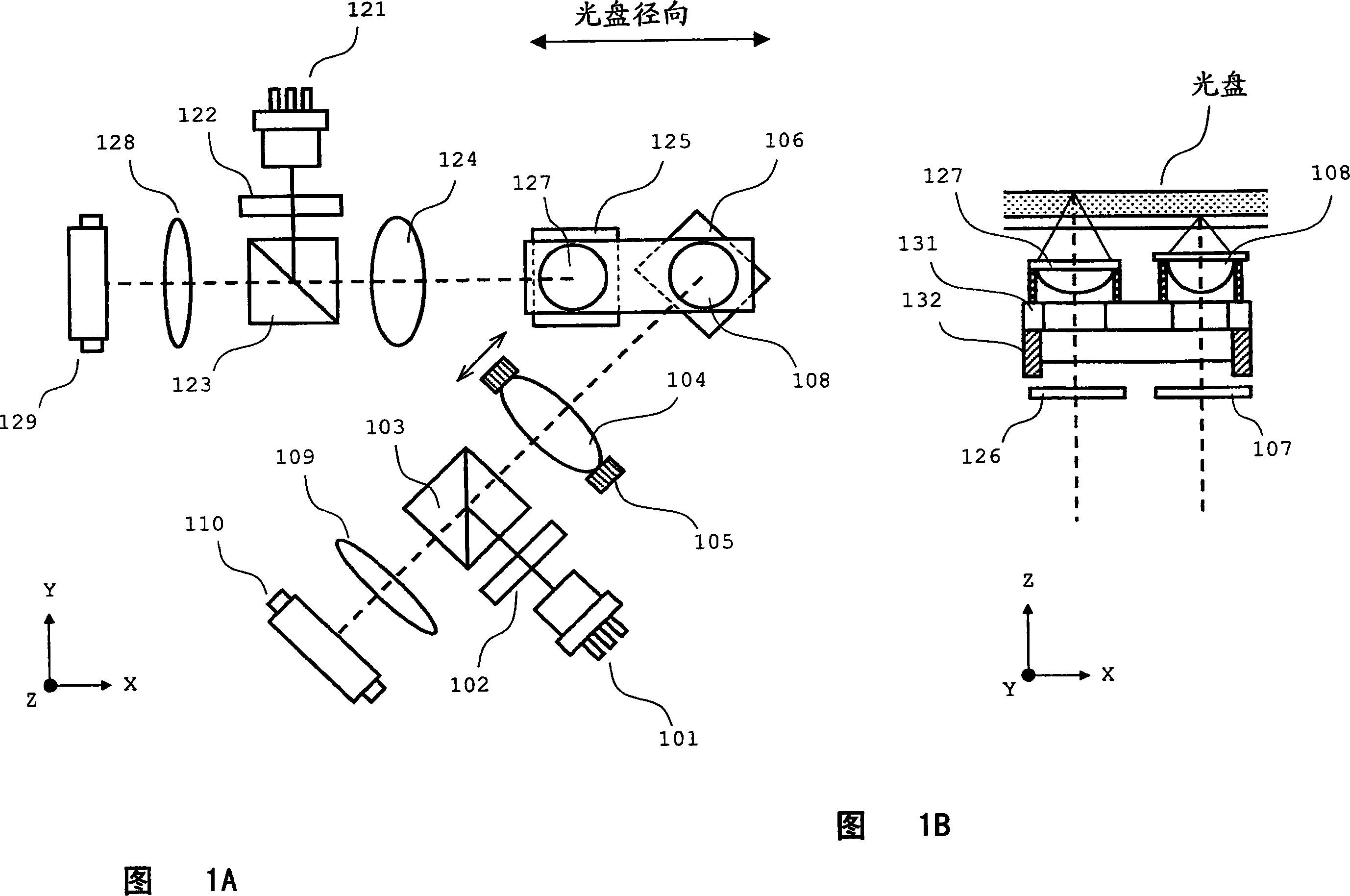
[0039]1A and B show the optical system of the optical pickup of the embodiment. FIG. 1A is a plan view of an optical system, and FIG. 1B is a side view of a peripheral portion of an objective lens actuator. This optical system is classified into an optical system for next-generation DVDs and an optical system for CDs.

[0040] The optical system for the next-generation DVD consists of a semiconductor laser 101, a diffraction grating 102, a polarizing beam splitter 103, a collimator lens 104, a lens actuator 105, a rising mirror (rising mirror) 106, a λ / 4 plate 107, a first An objective lens 108, an anamorphic lens (anamorphic lens) 109, and a photodetector 110 are constituted.

[0041] The semiconductor laser 101 outputs blue laser light with a wavelength of about 400 nm. The diffraction grating 102 divides the laser light emitt...

Embodiment 2

[0081] In this embodiment, the present invention is applied to an optical disc device for recording and reproducing next-generation DVDs, DVDs, and CDs.

[0082] The optical system of the optical pickup of the embodiment is shown in FIGS. 8A and 8B. FIG. 8A is a plan view of the optical system, and FIG. 8B is a side view of the peripheral portion of the objective lens actuator. The optical system is classified into an optical system for next-generation DVD and an optical system for CD / DVD.

[0083] The optical system for CD / DVD is composed of a diffraction grating 122 , a polarizing beam splitter 123 , a collimator lens 124 , a rising mirror 125 , an anamorphic lens 128 , a photodetector 129 , a semiconductor laser 144 , and a second objective lens 145 . Here, the semiconductor laser 144 emits laser light of an infrared wavelength with a wavelength of about 780 nm and laser light of a red wavelength with a wavelength of about 650 nm. The second objective lens 145 condenses t...


PUM

PropertyMeasurementUnit
wavelengthaaaaaaaaaa
thicknessaaaaaaaaaa
refractive indexaaaaaaaaaa

Abstract

The present invention provides an optical disc device. Two objective lenses are attached to a common holder. The holder is driven by an objective lens actuator, which integrally drives the two objective lenses. At this point, the objective lens (first objective lens) having a smaller diameter is arranged on a disk inner circumference side. In labeling, a reference pattern located at an inner circumference position is irradiated with a laser beam through the inner circumference-side first objective lens to obtain a gain which is used to finely move an objective lens actuator in a disk radial direction. The disk is irradiated with the laser beam through the second objective lens to generate an image in a disk surface while the objective lens actuator is driven with the gain.

Description

technical field [0001] The present invention relates to an optical disc device for labeling an optical disc using laser light emitted from an optical pickup, and is particularly suitable for use in an optical disc device equipped with an interchangeable optical pickup provided with a plurality of objective lenses. Background technique [0002] Conventionally, various methods are known as techniques for labeling optical discs. Among them, a technique of labeling an optical disc using laser light from an optical pickup is used as a labeling method for CD (Compact Disc: Compact Disc) and DVD (Digital Versatile Disc: Digital Versatile Disc). [0003] In this labeling technique, the optical disk is set in a driven state with the front and back reversed to the state at the time of recording and reproduction. Then, by driving the labeling driver while inputting an image desired by the user, the image is recorded on the surface of the optical disc. At this time, the disc rotates a...

Claims


Application Information

Patent Timeline
Patent Type & Authority Applications(China)
IPC IPC(8): G11B7/08G11B23/40
CPCG11B7/13925G11B7/1376G11B7/1374G11B7/08505G11B7/0037B41J3/4071B41J2/442G11B23/40G11B2007/0006G11B7/085
Inventor 浅野贤二
Owner SANYO ELECTRIC CO LTD
Why Eureka
Try Eureka