Covering material, covered rectangular electric wire and electrical device

a technology of electric wire and covering material, applied in the direction of insulated conductors, cables, conductors, etc., can solve the problems of degrading the length of the naked rectangular electric wire which can be covered with a single piece of insulating film tape wound therearound becomes short, and the dielectric breakdown degrades etc., to suppress the degradation of the properties of the covered rectangular electric wire, increase the wire occupation rate of the covered

Inactive Publication Date: 2013-01-10
NITTO DENKO CORP +1
View PDF0 Cites 6 Cited by
  • Summary
  • Abstract
  • Description
  • Claims
  • Application Information

AI Technical Summary

Benefits of technology

[0080]Within a range not impairing the advantageous effects of the present invention, for example, the following heretofore known various additives can be appropriately mixed in the viscoelastic layer of the present invention, in addition to the aforementioned base polymer: a tackifier, a plasticizer, a dispersant, an antiaging agent, an antioxidant, a processing aid, a stabilizer, an antifoaming agent, a flame retardant, a thickener, a pigment, a softener and a filler.
[0081]The viscoelastic layer 12 has a thickness of preferably 1.0 μm or more and 25.0 μm or less and more preferably 3.0 μm or more and 15.0 μm or less. The thickness of the viscoelastic layer 12 falling within this range offers an advantage that an appropriate adhesiveness can be obtained.
[0082]Specifically, when the thickness of the viscoelastic layer 12 is 25.0 μm or less, it is possible to increase the wire occupation rate of the rectangular electric wire in the covered rectangular electric wire formed when the rectangular electric wire is covered with the covering material 10, and hence it is possible to more suppress the degradation of the properties of the covered rectangular electric wire. When the thickness of the viscoelastic layer 12 is 15.0 μm or less, it is possible to further suppress the degradation of the properties.
[0083]On the other hand, when the thickness of the viscoelastic layer 12 is 1.0 μm or more, it is possible to increase the degree of the adhesion to the rectangular electric wire, and hence it is possible to more suppress the gap formed between the rectangular electric wire and the covering material 10. When the thickness of the viscoelastic layer 12 is 3.0 μm or more, it is possible to furthermore suppress the gap formed between the rectangular electric wire and the covering material 10.
[0084]The covering material 10 has a thickness of preferably 13.0 μm or more and 40.0 μm or less, more preferably 15.5 μm or more and 40.0 μm or less. When the thickness of the covering material 10 is 13.0 μm or more, the covering material is sufficient in strength and excellent in handleability; when the thickness of the covering material 10 is 15.5 μm or more, the covering material is more sufficient in strength and more excellent in handleability. When the thickness of the covering material 10 is 40.0 μm or less, it is possible to increase the wire occupation rate of the rectangular electric wire in the covered rectangular electric wire formed when the rectangular electric wire is covered with the covering material, and hence it is possible to more suppress the degradation of the properties of the covered rectangular electric wire.
[0085]The covering material 10 preferably has a width of one or more times and two or less times the width of the rectangular electric wire to be covered, from the viewpoint that when the rectangular electric wire is covered with the covering material 10 spirally wound around the rectangular electric wire, it is possible to make narrow the width of the lap portion and it is possible to reduce the angle between the extension direction of the naked rectangular electric wire and the winding direction of the insulating film tape. The width of such a covering material 10 is, for example, preferably 1 mm or more and 80 mm or less, more preferably 1.5 mm or more and 60 mm or less and furthermore preferably 2 mm or more and 40 mm or less.

Problems solved by technology

However, in the covered rectangular electric wire of the Patent Document 1, for the purpose of increasing the insulation property of the naked rectangular electric wires, it is necessary to provide a lap portion formed by partial overlap of the insulating film tape with itself; sometimes a space occurs in the lap portion, or sometimes the insulating film tape dose not sufficiently adhere to the naked rectangular electric wires and hence the lap portion includes air bubbles.
This phenomenon is referred to as partial discharge, and offers a problem such that the partial discharge degrades the insulating film tape, and a long-term use of the insulating film tape sometimes results in dielectric breakdown to degrade the properties of the covered rectangular electric wire.
Accordingly, the use of a superconducting wire as the rectangular electric wire also offers a problem such that the properties of the covered rectangular electric wire is degraded due to the partial discharge ascribable to the air bubbles or the space in the lap portion.
However, in the case where the width of the lap portion, namely, the overlap width of the insulating film tape is wide, when the insulating film tape is spirally wound around the naked rectangular electric wire, the length of the naked rectangular electric wire which can be covered with a single piece of the insulating film tape wound therearound becomes short.
However, also in this case, when the insulating film tape is spirally wound around the naked rectangular electric wire, the length of the naked rectangular electric wire which can be covered with a single piece of the insulating film tape wound therearound becomes short.

Method used


Image

  • Covering material, covered rectangular electric wire and electrical device
  • Covering material, covered rectangular electric wire and electrical device
  • Covering material, covered rectangular electric wire and electrical device

Examples


embodiment 1

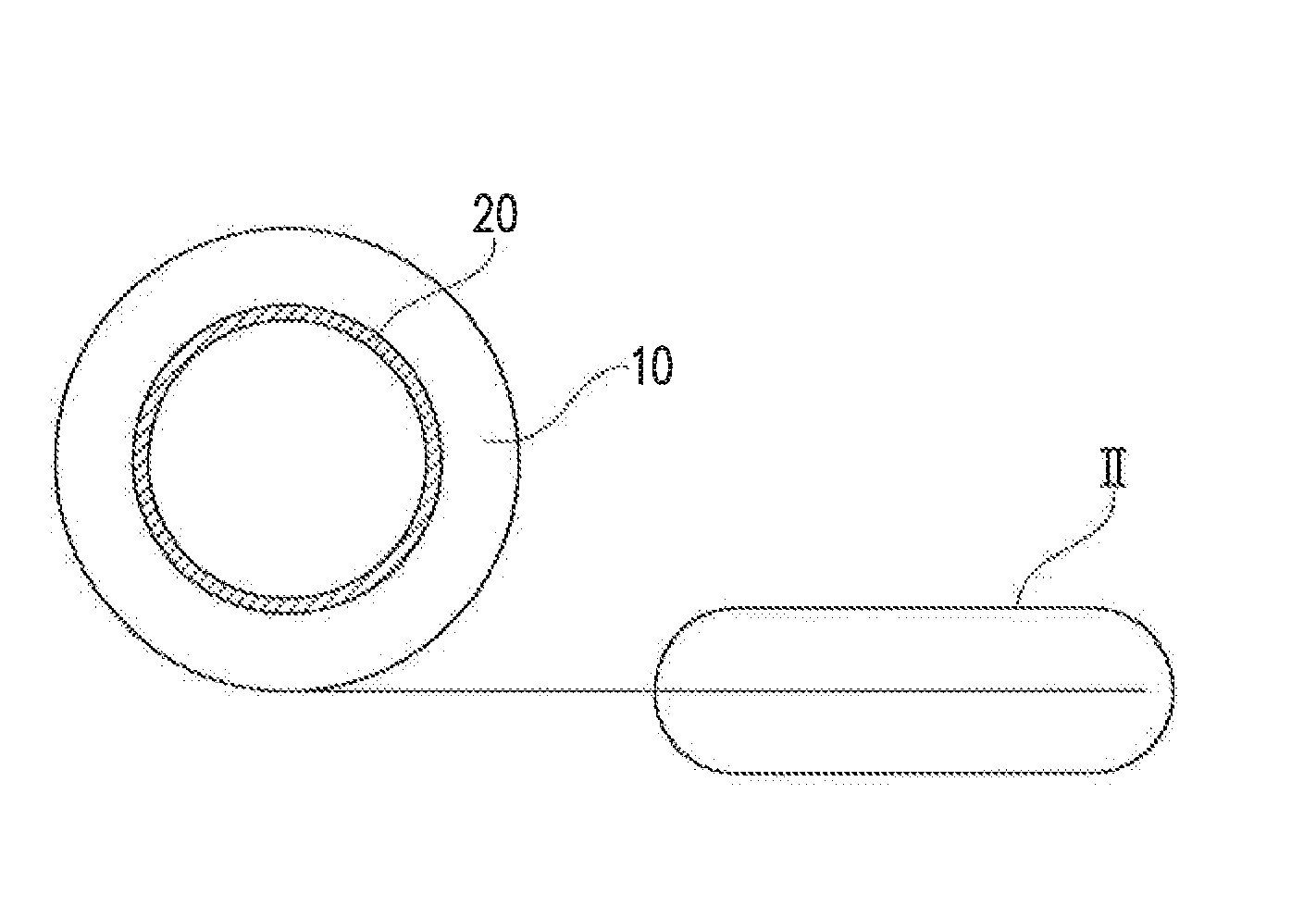
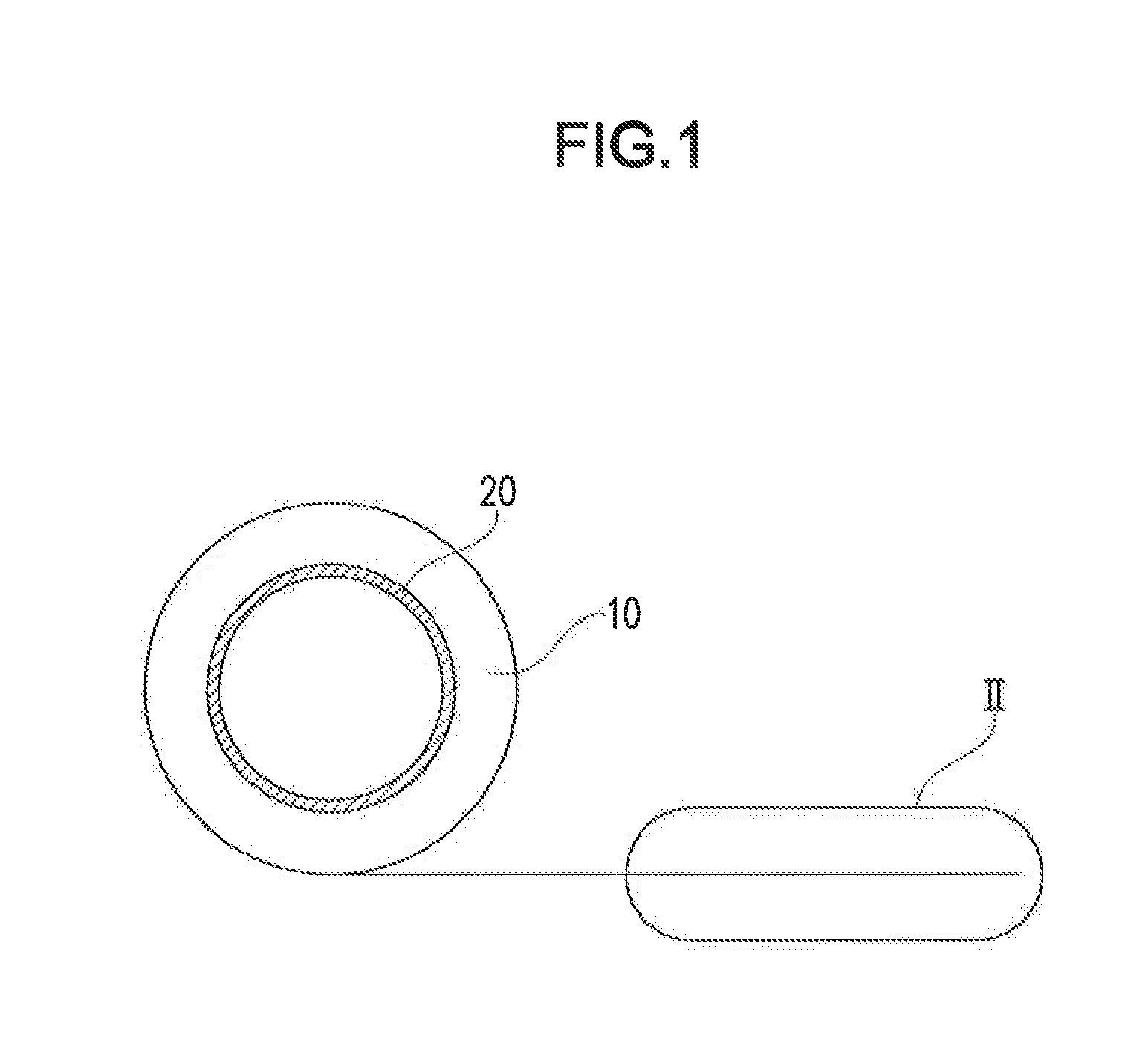
[0041]With reference to FIGS. 1 and 2, the covering material in one embodiment of the present invention is described. As shown in FIGS. 1 and 2, the covering material 10 in Embodiment 1 of the present invention is a covering material for covering a rectangular electric wire.

[0042]As shown in FIG. 1, the covering material 10 in the present embodiment is of a tape shape, and is, for example, wound around a winding core 20 in a roll shape. The covering material 10 is not limited to a tape shape, but may also take any other shapes such as a sheet shape and a film shape.

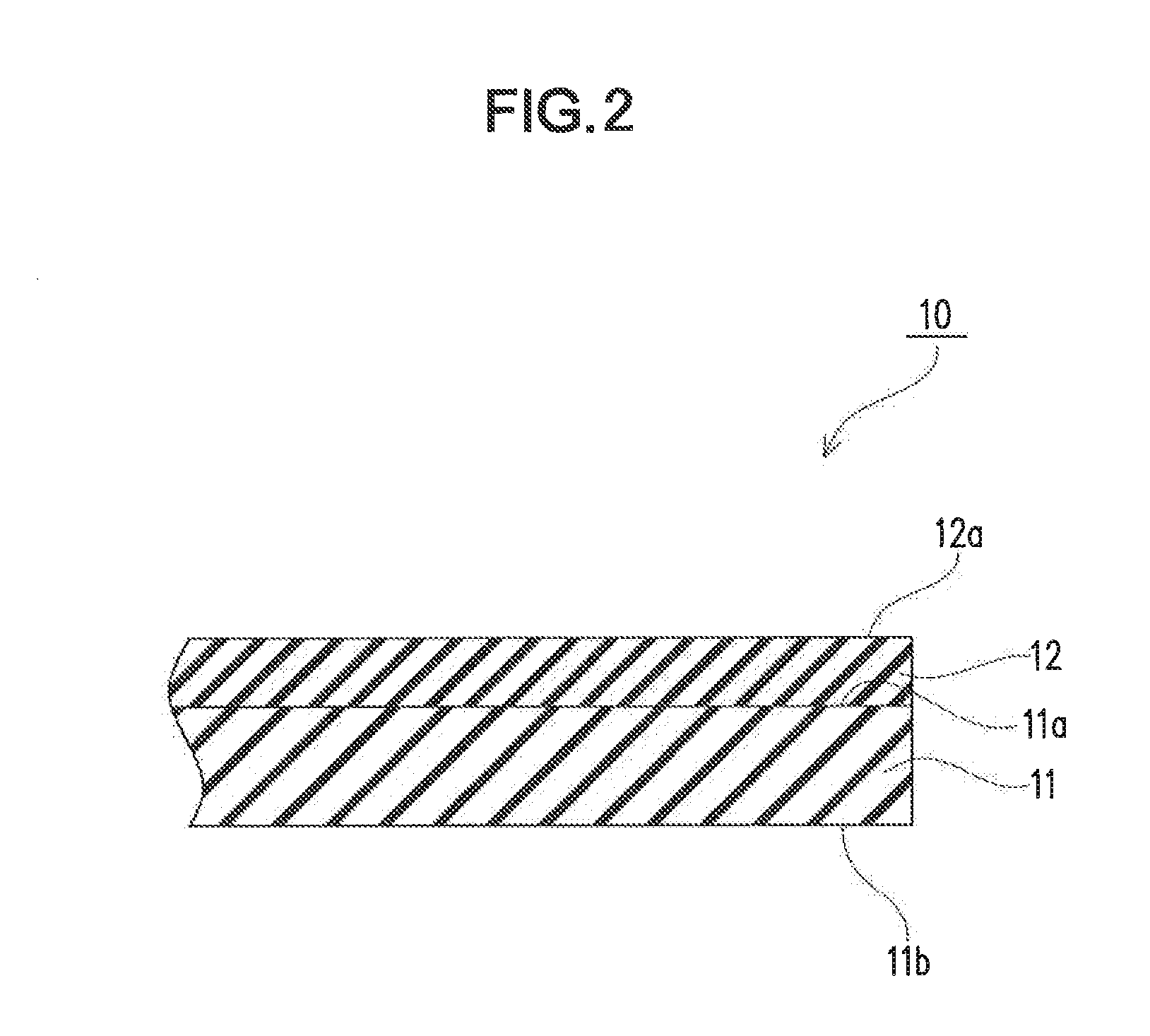
[0043]As shown in FIG. 2, the covering material 10 includes a backing 11 having an upper surface 11a and a lower surface 11b opposite to the upper surface 11a, and a viscoelastic layer 12 formed on the upper surface 11a of the backing 11. Another layer may be further formed between the backing 11 and the viscoelastic layer 12. On the upper surface 12a of the viscoelastic layer 12, a release liner (not shown) for protectin...

embodiment 2

[0099]With reference to FIGS. 3 to 7, the covered rectangular electric wire 100 in Embodiment 2 of the present invention is described. As shown in FIG. 3, the covered rectangular electric wire 100 in the present embodiment includes the covering material 10 of Embodiment 1 and a rectangular electric wire 110 covered with this covering material 10.

[0100]The mode of the covering of the rectangular electric wire 110 with the covering material 10 is not particularly limited; the covering material 10 may be spirally wound, or may be wound in such a way that the rectangular electric wire 110 runs along the lengthwise direction of the covering material 10 (so as to be attached in the longitudinal direction). As shown in FIGS. 3 to 5, the rectangular electric wire 110 in the present embodiment is covered with the covering material 10 in such a way that the covering material 10 is spirally wound around the rectangular electric wire 110.

[0101]Here, a preferable mode of spirally winding the rec...

embodiment 3

[0117]With reference to FIG. 8, description is made on a coil 200 as an example of the electrical device in Embodiment 3 of the present invention. As shown in FIG. 8, the coil 200 of the present embodiment includes a reel 210 and the covered rectangular electric wire 100 of Embodiment 2 wound around the reel 210.

[0118]The reel 210 is not particularly limited as long as the covered rectangular electric wire 100 can be wound around the reel 210; however, examples of the reel 210 include a cylindrical type and a racetrack type. The covered rectangular electric wire 100 may be a string, or may be formed of a plurality of strings connected to each other according to the required length. The coil may be formed of a plurality of laminated coils 200.

[0119]The production method of the coil 200 in Embodiment 3 includes a step of preparing the reel 210, and a step of winding the covered rectangular electric wire 100 around the reel 210.

[0120]In the present embodiment, the coil 200 is described...


PUM


Abstract

Provided is a covering material, which includes a backing having an upper surface and a lower surface opposite to the upper surface, and a viscoelastic layer formed on the upper surface of the backing, in which the covering material is a covering material for covering a rectangular electric wire, and an adhesive force of the viscoelastic layer to the lower surface of the backing as measured by peeling at a peeling angle of 180° and a tensile rate of 300 mm / min is 0.05 N / 20 mm or more and 10 N / 20 mm or less. A covered rectangular electric wire includes the covering material and a rectangular electric wire covered with the covering material. An electrical device is produced by using the covered rectangular electric wire.

Description

CROSS REFERENCE TO RELATED APPLICATION[0001]The present application claims priority of Japanese Patent Application No. 2011-151056, which is incorporated in the specification of the present application by reference.BACKGROUND OF THE INVENTION[0002]1. Field of the Invention[0003]The present invention relates to a covering material, a covered rectangular electric wire and an electrical device.[0004]2. Description of the Related Art[0005]In coil devices such as rotary devices and magnets to be used in electrical devices, there have been used covered rectangular electric wires obtained by covering rectangular electric wires with insulating covering materials. As the rectangular electric wires, there have hitherto been used wires made of copper, copper alloys, aluminum, aluminum alloys, and combinations of two or more of these metals; recently, for example, bismuth-based, yttrium-based and niobium-based superconducting wires have been used.[0006]Examples of such a covered rectangular ele...

Claims


Application Information

Patent Timeline
Patent Type & Authority Applications(United States)
IPC IPC(8): H01B7/00H01B17/00
CPCH01B3/46
Inventor MATSUSHITA, KIICHIROHANAI, HIROOMIHAYASHI, KAZUNORIFUJIKI, JUNOOHASHI, AKIHIROTAKAYANAGI, KAYOKOMUKOBATA, KAZUMASA
Owner NITTO DENKO CORP
Why Eureka
Try Eureka