Seal member, unit, and image forming apparatus

a technology of seal objects and parts, applied in the field of seal objects, can solve the problems of insufficient seal performance, inability to exhibit seal performance with respect to a stepped portion formed by the blade tip, and difficulty in producing perfect seal performance with respect to two members with different properties as seal objects

Active Publication Date: 2017-08-03
CANON KK
View PDF2 Cites 5 Cited by
  • Summary
  • Abstract
  • Description
  • Claims
  • Application Information

AI Technical Summary

Benefits of technology

[0030]According to the present invention, an occurrence of a gap that causes leakage of a developer in a developer housing portion can be more effectively suppressed.

Problems solved by technology

As described above, producing perfect seal performance with respect to two members with different properties as seal objects is no easy task.
In particular, since it is difficult to arrange the seal member all the way to a corner portion of a stepped portion formed by a blade tip and the rotating body, sufficient seal performance may not always be exhibited.
H04-243277, while seal performance can be expected with respect to a rotating body, there is a possibility that seal performance cannot be exhibited with respect to a stepped portion formed by the blade tip and the rotating body described above.
H07-013390, there is a possibility that sufficient seal performance cannot be exhibited with respect to the stepped portion and particularly all the way to a corner portion thereof.

Method used


Image

  • Seal member, unit, and image forming apparatus
  • Seal member, unit, and image forming apparatus
  • Seal member, unit, and image forming apparatus

Examples


first embodiment

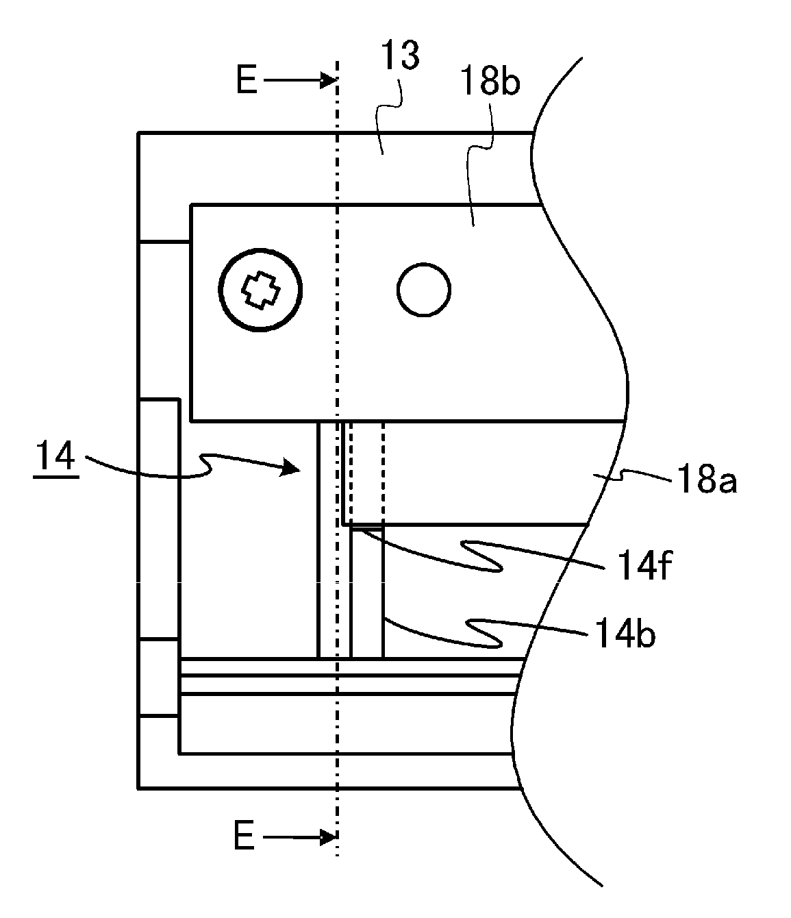
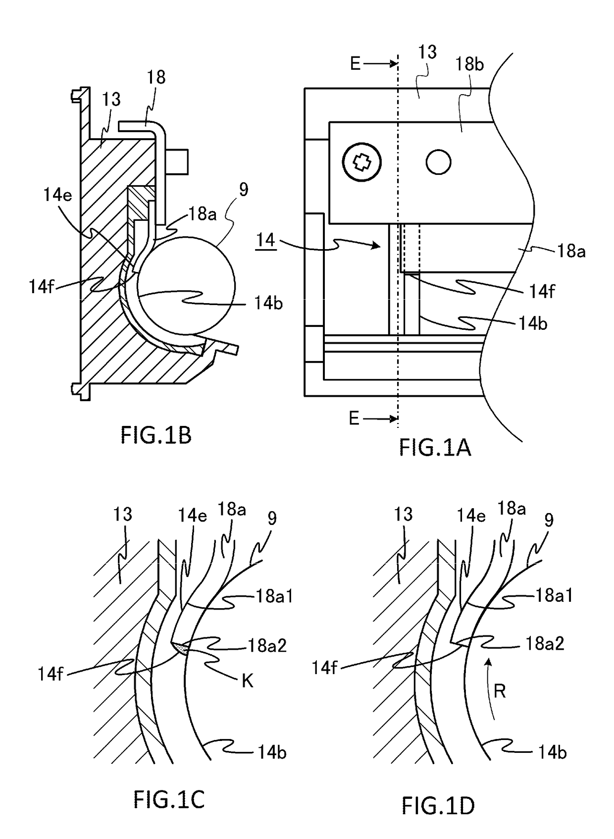
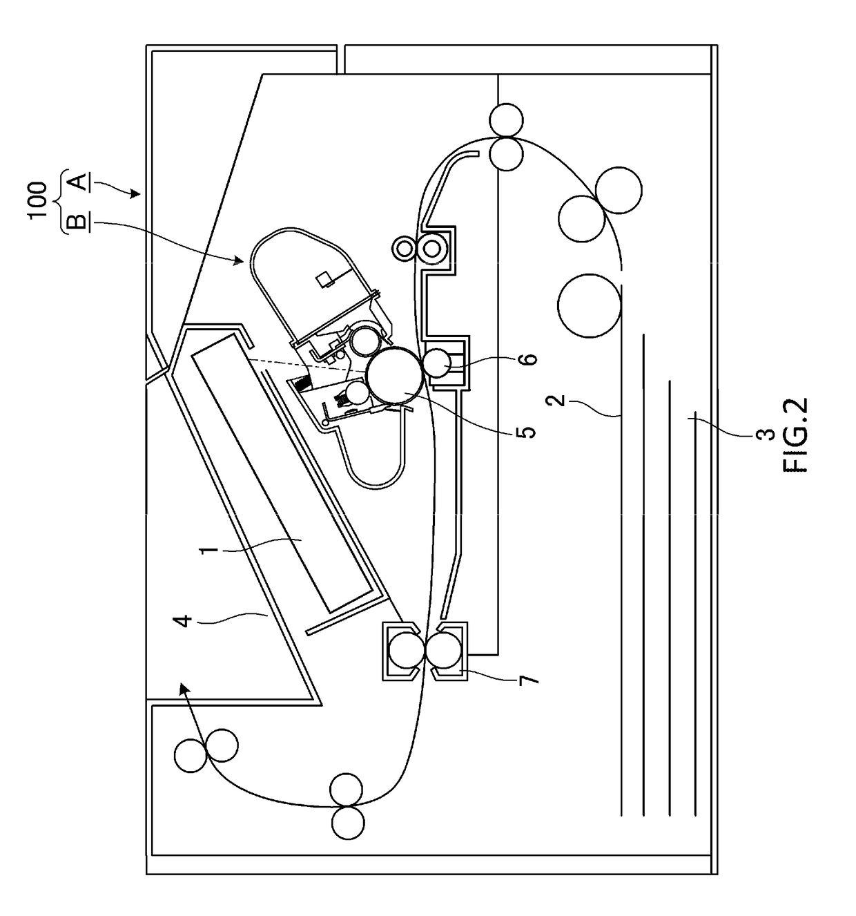
[0044]The present invention relates to a developing apparatus, a developing cartridge, and a process cartridge, and to an image forming apparatus using these components. A developing apparatus refers to an apparatus which includes a developing roller (a developer bearing member) that bears a developer on a surface thereof and which uses the developer to convert an electrostatic latent image (an electrostatic image) formed on a photosensitive drum (an image bearing member) by the developing roller into a visible image. A developing cartridge is the developing apparatus made into a cartridge as an integrated unit and is attachably and detachably mounted to an image forming apparatus main body. In addition, a process cartridge refers to a cartridge made up of a photosensitive drum and a developing apparatus that acts on the photosensitive drum as an integrated unit and is attachably and detachably mounted to an image forming apparatus main body. Furthermore, an image forming apparatus ...

second embodiment

[0064]A configuration of a second embodiment of the present invention will now be described with reference to FIGS. 6A to 8. FIGS. 6A to 6C are diagrams showing the seal member 14 shown in FIGS. 5A to 5C being replaced by a seal member 24 according to the present embodiment. In a similar manner, FIGS. 7A to 7D are diagrams showing the seal member 14 shown in FIGS. 1A to 1D being replaced by the seal member 24, and FIG. 8 is a diagram showing the seal member 14 shown in FIG. 4 being replaced by the seal member 24. In the second embodiment, components in common with those of the first embodiment are assigned same reference characters and descriptions thereof will be omitted. Matters not described in the second embodiment are similar to those described in the first embodiment.

[0065]As shown in FIG. 6A, a stepped portion 24f of the seal member 24 according to the present embodiment has a shape that is more elongated in an outer side direction (a leftward direction in FIG. 6A) of the fra...

third embodiment

[0070]A configuration of a third embodiment of the present invention will now be described with reference to FIGS. 9A to 11B. FIGS. 9A to 9C are diagrams showing the seal member 24 shown in FIGS. 6A to 6C being replaced by a seal member 34 according to the present embodiment. In a similar manner, FIGS. 10A to 10D are diagrams showing the seal member 24 shown in FIGS. 7A to 7D being replaced by the seal member 34, and FIG. 11A is a diagram showing the seal member 24 shown in FIG. 8 being replaced by the seal member 34. In addition, FIG. 11B is a diagram showing an enlargement of a periphery of the seal member 34 shown in FIG. 11A. In the third embodiment, components in common with those of the first and second embodiments are assigned same reference characters and descriptions thereof will be omitted. Matters not described in the third embodiment are similar to those described in the first and second embodiments.

[0071]As shown in FIGS. 9A and 11B, the stepped portion 34f of the seal ...


PUM


Abstract

A seal member 14 which seals a gap among a rotating body 9 provided in an opening of a frame body 13, a blade 18a, and the frame body 13 in an end region in an axial direction of the rotating body 9, the seal member 14 including: a first seal portion 14b which comes into contact with the rotating body 9; a second seal portion 14e which comes into contact with the blade 18a; and a third seal portion 14f which is constituted by a surface formed in a stair shape and sequentially arranged between the first seal portion 14b and the second seal portion 14e and which is capable of reducing a gap formed between the rotating body 9 and the blade 18a due to rotation of the rotating body 9.

Description

BACKGROUND OF THE INVENTION[0001]Field of the Invention[0002]The present invention relates to a seal member in an image forming apparatus and in a process cartridge.[0003]Description of the Related Art[0004]Units such as a developing apparatus and a process cartridge which constitute an electrophotographic image forming apparatus (hereinafter, an image forming apparatus) are configured such that a cleaning blade, a developing blade, and the like are brought into contact with a rotating body such as a photosensitive drum and a developing roller. With such units, in order to prevent a developer from leaking, a seal member is provided at ends in an axial direction of a rotary shaft of a photosensitive drum, a developing roller, and the like. Seal members using an elastic body such as an elastomer are known as such seal members (for example, refer to Japanese Patent Application Laid-open No. H04-243277 and Japanese Patent Application Laid-open No. H07-013390).SUMMARY OF THE INVENTION[00...

Claims


Application Information

Patent Timeline
Patent Type & Authority Applications(United States)
IPC IPC(8): G03G15/08
CPCG03G15/0898G03G15/0817
Inventor SASAKI, HIRAKUMATSUZAKI, HIROOMIMATSUMOTO, KAZUKI
Owner CANON KK
Why Eureka
Try Eureka