Antenna apparatus for radio communication

a technology of antenna apparatus and antenna, applied in the direction of antenna, non-resonant long antenna, electrically long antenna, etc., can solve the problem that the small patch antenna cannot sufficiently lower the intensity of electric waves radiated toward the back side of the antenna, and achieve the effect of lowering the intensity of electric waves radiated

Inactive Publication Date: 2010-12-21
NIPPON SOKEN +1
View PDF14 Cites 40 Cited by
  • Summary
  • Abstract
  • Description
  • Claims
  • Application Information

AI Technical Summary

Benefits of technology

[0009]An object of the present invention is to provide, with due consideration to the drawbacks of the conventional antenna, an antenna apparatus which is downsized and has specific radiation characteristics so as to sufficiently lower the intensity of electric waves radiated in the back direction of the antenna apparatus.
[0013]In a conventional antenna apparatus having no high impedance ground plane, a linear antenna is disposed over a ground plane having no high impedance for an alternating current of the specific frequency band. When an alternating current of the specific frequency band flows through this linear antenna, an image current having the same frequency as that of the alternating current flows through the ground plane in response to the alternating current so as to cancel out the alternating current of the antenna. That is, a mirror image (i.e., reverse image) is formed in the ground plane. Therefore, radiation characteristics of the antenna receiving electromagnetic waves based on the image current are degraded. Further, as the antenna approaches the ground plane, the image current induced in the ground plane is increased. Therefore, to prevent this problem in the conventional antenna apparatus, the antenna is disposed to be sufficiently far away from the ground plane. However, electric waves radiated from the antenna are easily directed in the back direction of the antenna apparatus at a high intensity.
[0015]Further, because the antenna is disposed close to the ground plane, the antenna apparatus prevents electromagnetic waves from propagating over the surface of the ground plane so as to leak toward the back side of the ground plane opposite to the first side. Therefore, the antenna apparatus substantially suppresses electromagnetic waves leaked toward the back side of the ground plane. In the conventional antenna apparatus, to reduce leakage of electromagnetic waves toward the back side of the ground plane, it is required to enlarge the size of the ground plane in the face directions perpendicular to the thickness direction. Accordingly, the antenna apparatus according to this invention can efficiently suppress leakage of electromagnetic waves in the back side of the ground plane while downsizing the ground plane in the face directions. That is, the antenna apparatus has specific radiation characteristics so as to sufficiently lower the intensity of electric waves radiated in the back direction of the antenna apparatus.

Problems solved by technology

Therefore, a small-sized patch antenna cannot sufficiently lower the intensity of electric waves radiated toward the back side of the antenna.

Method used


Image

  • Antenna apparatus for radio communication
  • Antenna apparatus for radio communication
  • Antenna apparatus for radio communication

Examples


embodiment 1

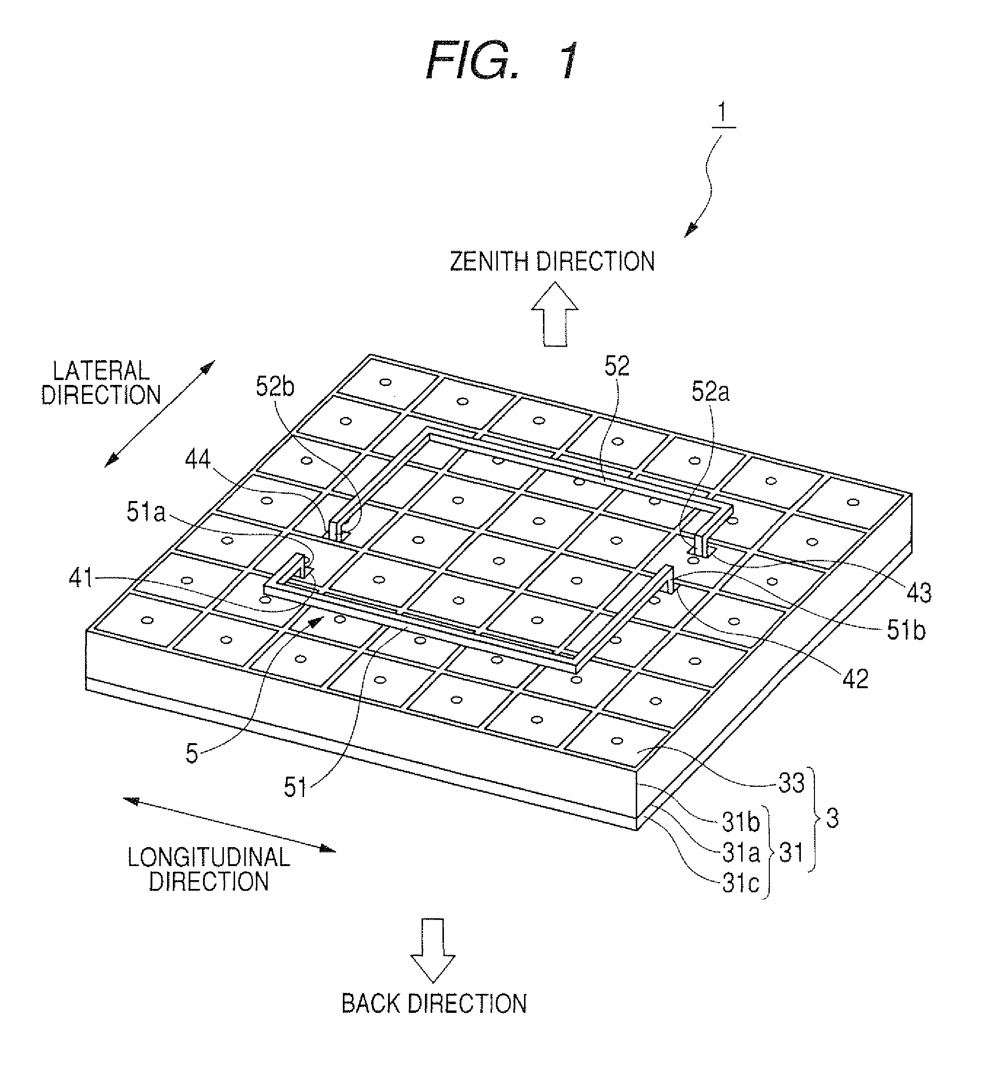
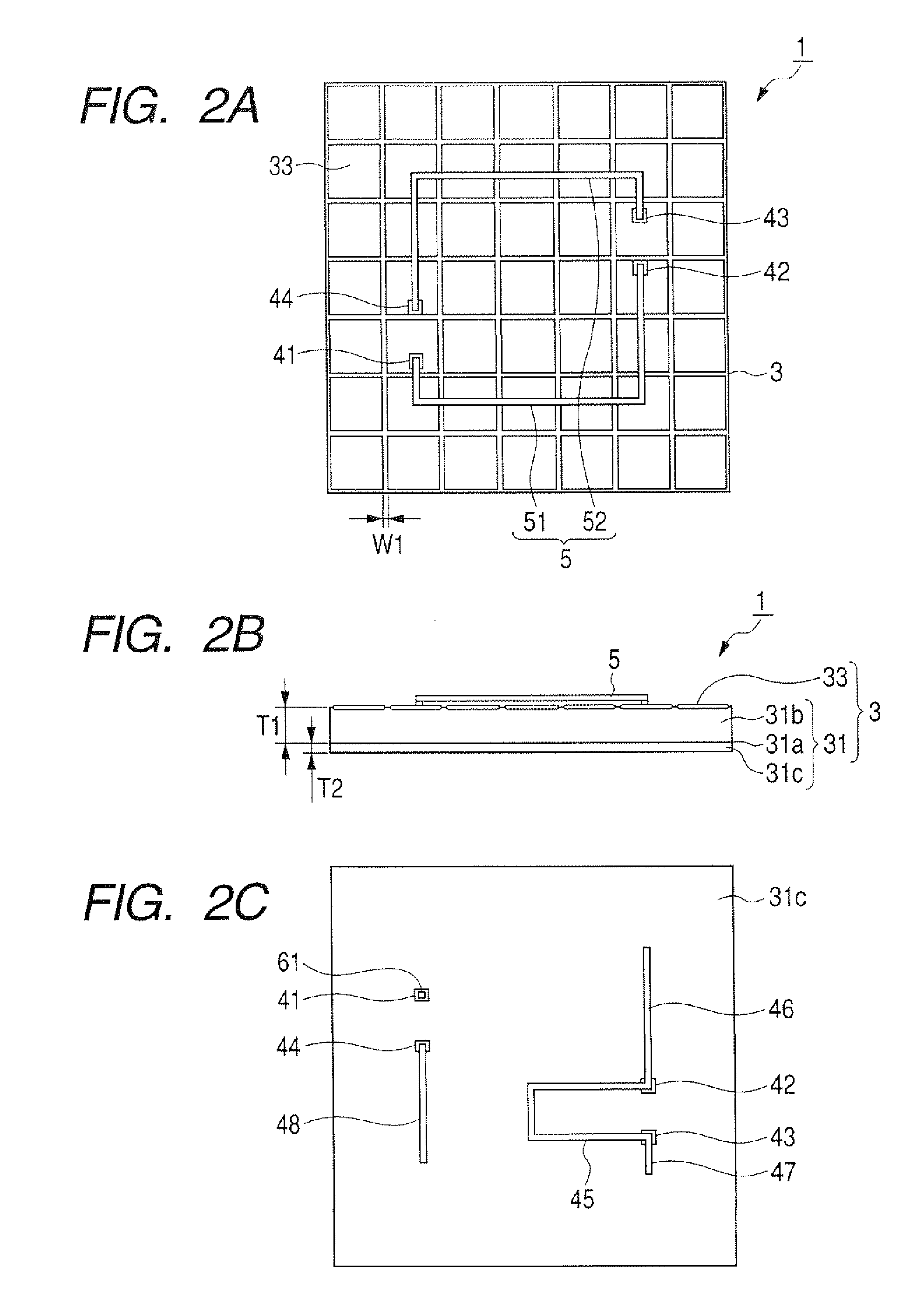
[0050]FIG. 1 is a perspective side view of an antenna apparatus according to the first embodiment. FIG. 2A is a front view of the antenna apparatus shown in FIG. 1, FIG. 2B is a side view of the antenna apparatus shown in FIG. 1, and FIG. 2C is a back view of the antenna apparatus shown in FIG. 1.

[0051]As shown in FIG. 1 and FIG. 2A, an antenna apparatus 1 has a ground plane 3 formed in a rectangular parallelepiped and a radiation element 5 radiating electromagnetic waves. As described later in detail, the ground plane 3 has an electromagnetic band gap surface (or an electromagnetic band gap plate) on the front side of the ground plane 3. The band gap surface is conductive and has a high impedance for an alternating current of a specific frequency band to substantially prevent propagation of electromagnetic waves set within the specific frequency band.

[0052]The radiation element 5 has a first linear antenna 51 and a second linear antenna 52 paired with each other. The antennas 51 an...

embodiment 2

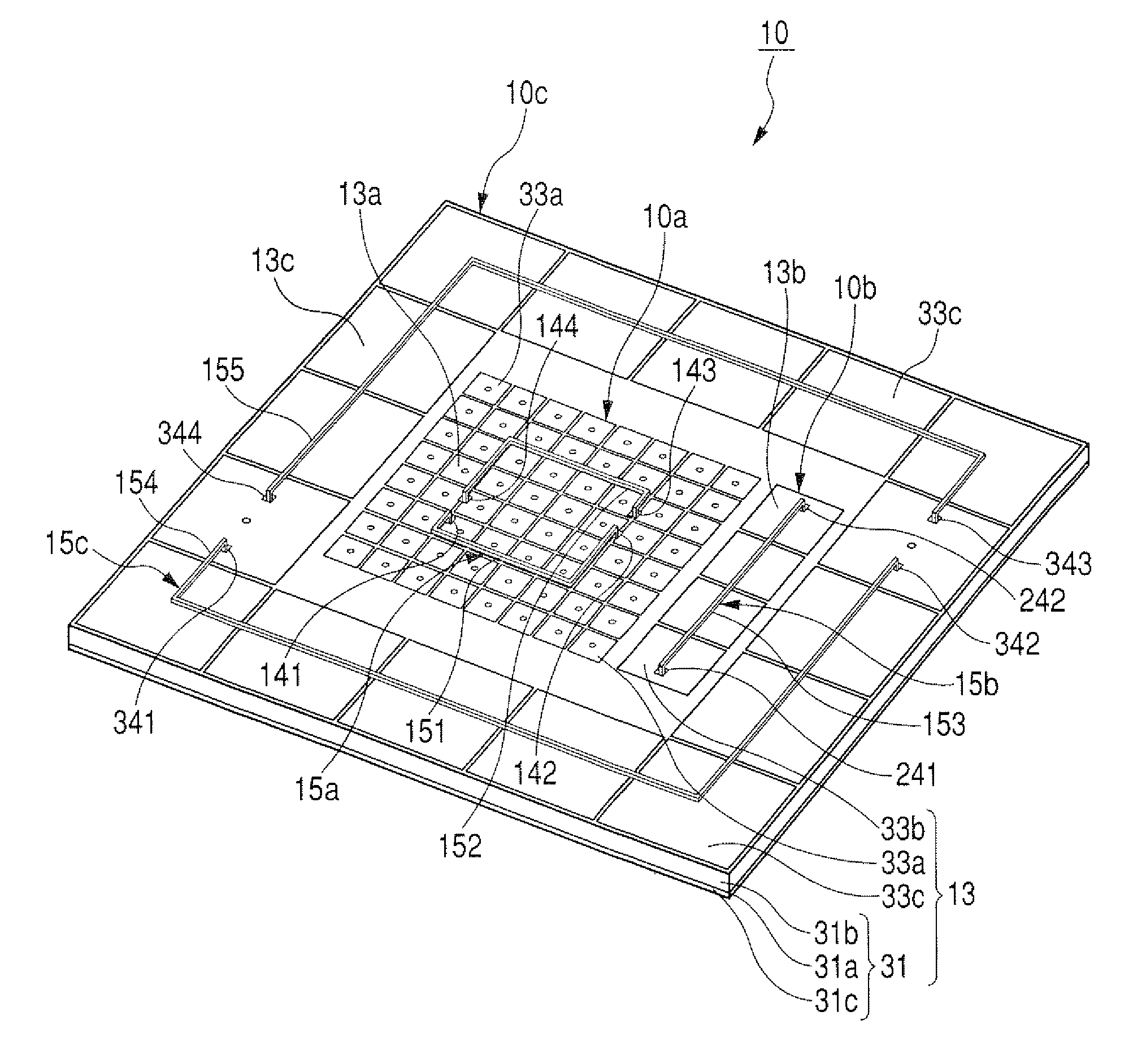
[0093]FIG. 7 is a perspective side view of an antenna apparatus according to the second embodiment. FIG. 5A is a front view of the antenna apparatus shown in FIG. 7. FIG. 5B is a side view of the antenna apparatus shown in FIG. 7. FIG. 9 is a back view of the antenna apparatus shown in FIG. 7.

[0094]As shown in FIG. 7, FIG. 8A, FIG. 8B, and FIG. 9, an antenna apparatus 10 has a ground plane 13 formed in a rectangular parallelepiped and a radiation section 15 radiating and receiving electromagnetic waves. The ground plane 13 is partitioned into a first ground plane portion 13a disposed in the center of the ground plane 13, a second ground plane portion 13b disposed on one side (left side in FIG. 8A) of the portion 13a, and a third ground plane portion 13c disposed on the periphery of the ground plane 13 so as to surround the portions 13a and 13b. The plane portions 13a to 13c are spaced from one another through dielectric (or insulating) parts of the ground plane 13. As described late...

embodiment 3

[0117]FIG. 14 is a front view of an antenna apparatus according to the third embodiment, while FIG. 15 is a sectional view taken substantially along line A-A of FIG. 14. FIG. 16 is a back view of the antenna apparatus shown in FIG. 14.

[0118]As shown in FIG. 14, FIG. 15 and FIG. 16, an antenna apparatus 100 has a ground plane 103 formed in a rectangular parallelepiped, a radiation element 105 radiating and receiving electromagnetic waves, and an antenna case 101. The case 101 accommodates the ground plane 103 and the radiation element 105 therein so as to surround four side surfaces and a bottom surface of the ground plane 103 and to expose a front surface of the ground plane 103 from an opening of the case 101. The case 101 is made of metal so as to prevent electromagnetic waves from being radiated from the element 105 toward the back side of the apparatus 100 while going around the side surfaces of the ground plane 103. The radiation element 105 has the linear antennas 51 and 52 di...


PUM


Abstract

An antenna apparatus has a ground plane and a traveling-wave linear antenna The ground plane has a dielectric layer and metallic plates disposed on the dielectric layer. The plates placed on a front side of the ground plane act as a band gap surface. The dielectric constant and thickness of the dielectric layer, the number of plates and the width of spaces among the plates are adjusted, so that the band gap surface prevents propagation of electromagnetic waves within a specific frequency band. The antenna is disposed over the band gap surface on the front side of the ground plane to be spaced away from the band gap surface. The antenna radiates electromagnetic waves of an operational frequency within the specific frequency band in response to an alternating current of the operational frequency fed to the linear antenna.

Description

CROSS-REFERENCE TO RELATED APPLICATION[0001]This application is based upon and claims the benefit of priority of the prior Japanese Patent Application 2007-250002 filed on Sep. 26, 2007 and the prior Japanese Patent Application 2008-188591 filed on Jul. 22, 2008, so that the contents of which are incorporated herein by reference.BACKGROUND OF THE INVENTION[0002]1. Field of the Invention[0003]The present invention relates to an antenna apparatus having a ground plane and a linear antenna disposed on the ground plane.[0004]2. Description of Related Art[0005]As a system for radio-communicating between a base station and each of on-board terminal devices, a global positioning system and a system of an electronic toll collection are, for example, well known. In these systems, circularly polarized electric waves are used to reliably receive the electric waves in antennas of the terminal devices regardless of the coming direction of the electric waves. As antennas of the terminal devices r...

Claims


Application Information

Patent Timeline
Patent Type & Authority Patents(United States)
IPC IPC(8): H01Q11/02H01Q21/30
CPCH01Q1/241H01Q11/04H01Q21/068H01Q15/008
Inventor FUKUI, SHINJIFUJITA, MITSURU
Owner NIPPON SOKEN
Why Eureka
Try Eureka