Fuel cell system and method of detecting failure in a fuel gas channel of fuel cell system

a fuel cell system and gas channel technology, applied in the direction of fuel cells, solid electrolyte fuel cells, electrical equipment, etc., can solve problems such as water clogging

Active Publication Date: 2006-06-01
HONDA MOTOR CO LTD
View PDF0 Cites 40 Cited by
  • Summary
  • Abstract
  • Description
  • Claims
  • Application Information

AI Technical Summary

Benefits of technology

[0015] The present invention has been made taking the problems into consideration, and an object of the present invention is to provide a fuel cell system which makes it possible to detect a failure in a fuel gas channel in a short period of time after the end of operation of the fuel cell system, and to provide a method of detecting a failure in the fuel gas channel of the fuel cell system.
[0018] According to the present invention, when the operation of the fuel cell system is finished, the oxygen-containing gas which does not pass through the electrolyte membrane toward the cathode is contained in the fuel gas channel. The pressure decrease after the containment is detected to determine a failure in the fuel gas channel in a short period of time. Further, according to the present invention, after the oxygen-containing gas is contained in the fuel gas channel, only the oxygen-containing gas is present at the anode and the cathode. Therefore, unlike the case of the conventional technique, when power generation is stopped, it is possible to avoid the degradation of the performance due to the mixture of the oxygen-containing gas and the fuel gas.
[0020] In each of the inventions as described above, the pressure detection means and the failure determination means may not be used. Also in the case in which the pressure detection means and the failure determination means are not used, in particular, in the polymer electrolyte fuel cell, when the power generation is stopped (when the system is stopped), after the oxygen-containing gas which does not pass through the electrolyte membrane toward the cathode is contained in the fuel gas channel at a predetermined pressure, only the oxygen-containing gas is present at the anode and the cathode. Therefore, after the power generation is stopped (after the system is stopped), unlike the case of the conventional technique, it is possible to avoid the degradation of the performance due to the mixture of the oxygen-containing gas and the fuel gas.
[0022] According to the present invention, when the operation of the fuel cell system is finished, the oxygen-containing gas which does not pass through the electrolyte membrane toward the cathode is contained in the fuel gas channel at a predetermined pressure. The pressure decrease after the containment is detected to determine a failure due to leakage in the fuel gas channel in a short period of time.
[0025] In each of the inventions, when a failure is detected, restart of the fuel cell system is prohibited, or an alarm is issued for making it possible to prevent the degradation of the performance of the fuel cell, and suppress the leakage of the fuel gas to the outside as much as possible.
[0029] Further, in the present invention, after the power generation is stopped and the oxygen-containing gas is contained in the fuel gas channel, only the oxygen-containing gas is present at the anode and the cathode. Thus, unlike the case of the conventional technique, it is possible to avoid the degradation of the performance due to the mixture of the oxygen-containing gas and the fuel gas.

Problems solved by technology

If the water is excessively present at any of the electrodes, water clogging may occur.

Method used


Image

  • Fuel cell system and method of detecting failure in a fuel gas channel of fuel cell system
  • Fuel cell system and method of detecting failure in a fuel gas channel of fuel cell system
  • Fuel cell system and method of detecting failure in a fuel gas channel of fuel cell system

Examples


first embodiment

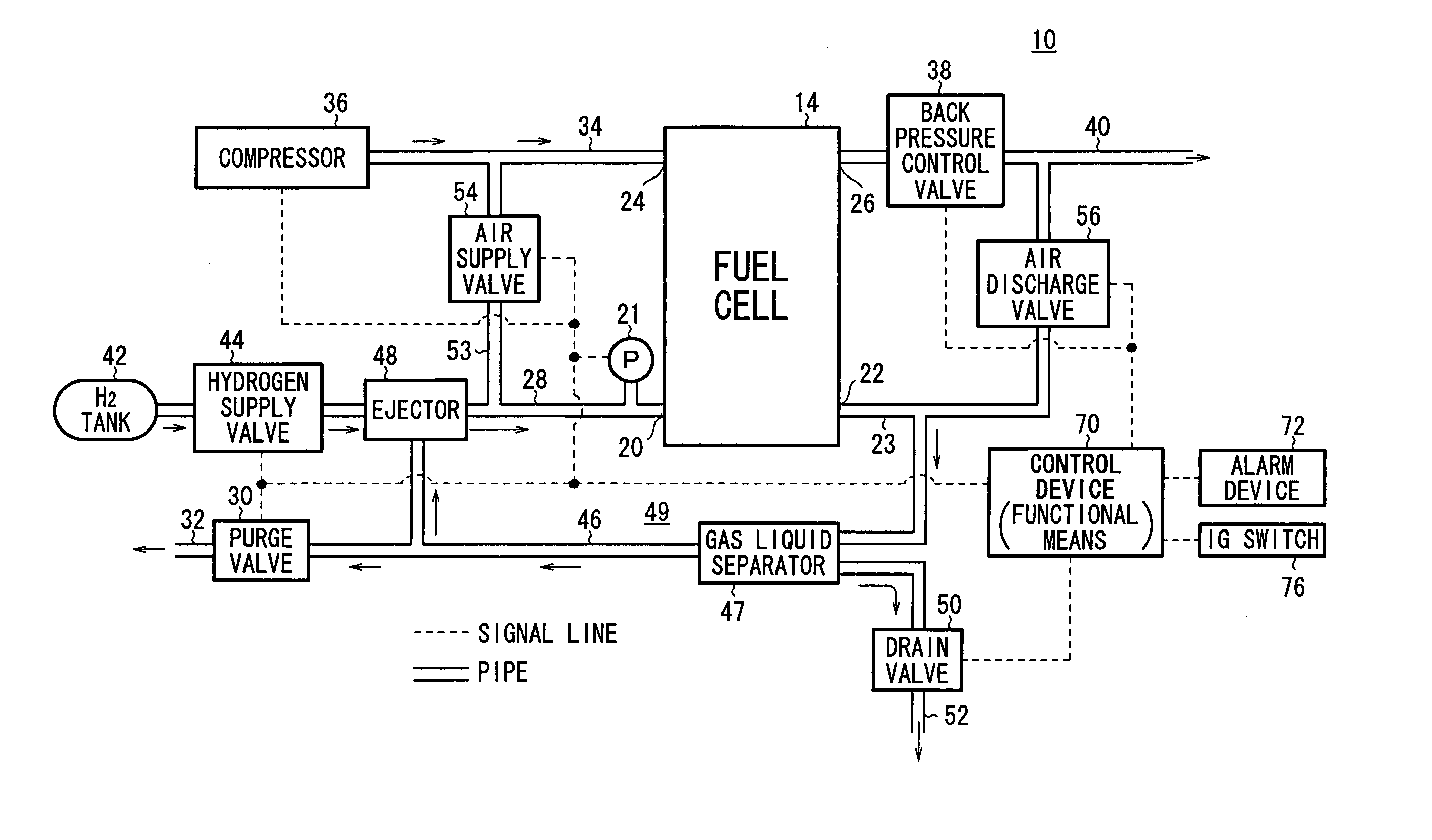
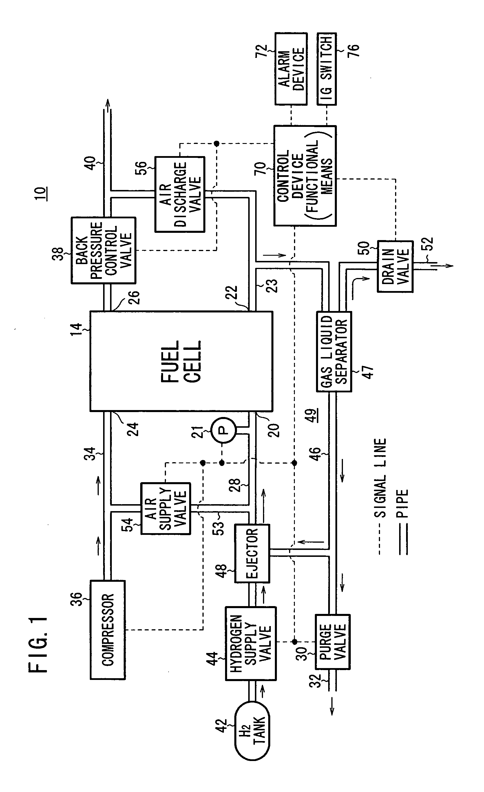
[0039]FIG. 1 is a diagram schematically showing structure of a fuel cell system 10 according to the present invention.

[0040] Basically, the fuel cell system 10 includes a fuel cell 14, a hydrogen tank 42 for supplying a hydrogen gas (H2) as a fuel gas to the fuel cell 14, and a compressor (air compressor) 36 for supplying a compressed air including, e.g., oxygen (O2) to the fuel cell 14.

[0041] The fuel cell 14 includes a membrane electrode assembly and a pair of separators sandwiching the membrane electrode assembly. The membrane electrode assembly includes an anode, a cathode, and a solid polymer electrolyte membrane interposed between the anode and the cathode. A fuel gas flow field is formed between the anode and one of the separators, and an oxygen-containing gas flow field is formed between the cathode and the other of the separators. A plurality of unit cells are stacked together to form the stack structure of the fuel cell 14.

[0042] The fuel cell 14 has a hydrogen supply po...

second embodiment

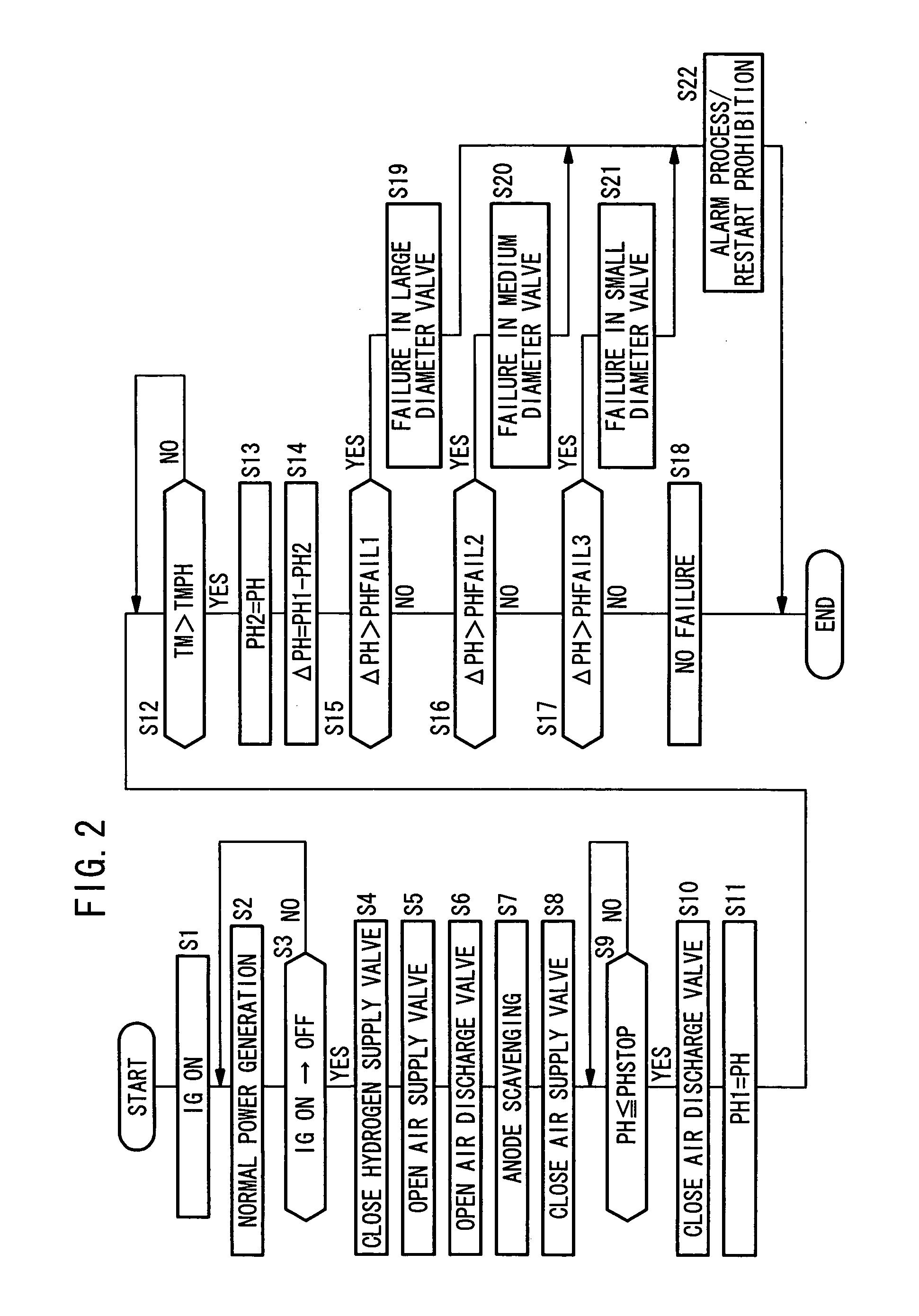
[0073] In the above-described embodiment, the failures of all the valves 30, 50, 54, and 56 connected to the fuel gas channel 49 can be detected separately. Alternatively, the structure may be changed in a second embodiment as shown in FIGS. 5 and 6. In the embodiment, a map in FIG. 6 for detecting the minute leakage in the drain valve 50 having the smallest diameter, the valve seat or the like is used, and the failure in any of the valves 30, 50, 54, and 56 can be detected at once in the determination of step S15′ and step S19′ in FIG. 5. In FIG. 5, the steps other than steps S15′ and S19′ are carried out in the same manner as the steps shown in FIG. 2.

[0074] The flow chart and the map in FIGS. 5 and 6 are applicable to the structure of a fuel cell system 10A shown in FIG. 4. In the fuel cell system 10A, the hydrogen purge valve 30, the ejector 48, the gas liquid separator 47, and the drain valve 50 are removed from the fuel gas channel 49 of the fuel cell system 10 according to th...


PUM

PropertyMeasurementUnit
pressureaaaaaaaaaa
chemicalaaaaaaaaaa
DC electrical energyaaaaaaaaaa

Abstract

When an ignition switch is turned off, a hydrogen supply valve is closed. Operation of a compressor continues, and an air supply valve and an air discharge valve are opened to supply the compressed air into a fuel cell through a hydrogen supply port. The scavenging process of removing the fuel gas and the water remaining in the fuel gas channel is performed through the air discharge valve, a drain valve, and a hydrogen purge valve. Then, all the valves connected to the fuel gas channel are closed. The pressure when the valves are closed, and the pressure when a short time has elapsed after closing the valves are detected by a pressure sensor. Based on the pressure difference, a failure due to the leakage in the fuel gas channel is detected.

Description

BACKGROUND OF THE INVENTION [0001] 1. Field of the Invention [0002] The present invention relates to a fuel cell system to which a technique for detecting a failure due to leakage in a fuel gas channel is applied, and a method of detecting a failure in the fuel gas channel of the fuel cell system. [0003] 2. Description of the Related Art [0004] For example, a polymer electrolyte fuel cell employs a membrane electrode assembly which includes an anode (fuel electrode) and a cathode (air electrode), and a polymer electrolyte membrane interposed between the electrodes. The electrolyte membrane is an ion exchange membrane. The membrane electrode assembly is sandwiched between a pair of separators. A fuel gas flow field is formed between the anode and one of the separators, and an oxygen-containing gas flow field is formed between the cathode and the other of the separators. In use, normally, a predetermined numbers of the membrane electrode assemblies and separators are stacked together ...

Claims


Application Information

Patent Timeline
Patent Type & Authority Applications(United States)
IPC IPC(8): H01M8/04H01M8/10
CPCH01M8/04164H01M8/04231H01M8/04238H01M2008/1095Y02E60/50
Inventor KOTANI, YASUNORIYOSHIKAWA, SHINJIYAMAMOTO, AKIOKOBAYASHI, TOMOKI
Owner HONDA MOTOR CO LTD
Why Eureka
Try Eureka