Storage system

a storage system and cache memory technology, applied in the field of storage systems, can solve problems such as the performance decline of other application programs, and achieve the effect of inhibiting performance deterioration and optimizing performance tuning of cache memory

Inactive Publication Date: 2006-08-17
HITACHI LTD
View PDF12 Cites 50 Cited by
  • Summary
  • Abstract
  • Description
  • Claims
  • Application Information

AI Technical Summary

Benefits of technology

[0014] Another object of the present invention is to provide, in a storage system which is shared by a plurality of application programs, a storage system which inhibits performance deterioration caused by a resource conflict of a cache memory between a plurality of application programs having different I / O characteristics or between a plurality of storage devices having different performance characteristics.

Problems solved by technology

In a conventional storage system, performance tuning for judging necessity of segment size settings or of dual writing in accordance with the I / O characteristics for each application program could not be performed, thus in a storage system which is shared by a plurality of application programs, when performing tuning for a cache memory which is optimum to a certain application program, there occurred a problem that the performances of other application programs decrease.

Method used


Image

  • Storage system
  • Storage system
  • Storage system

Examples


embodiment 1

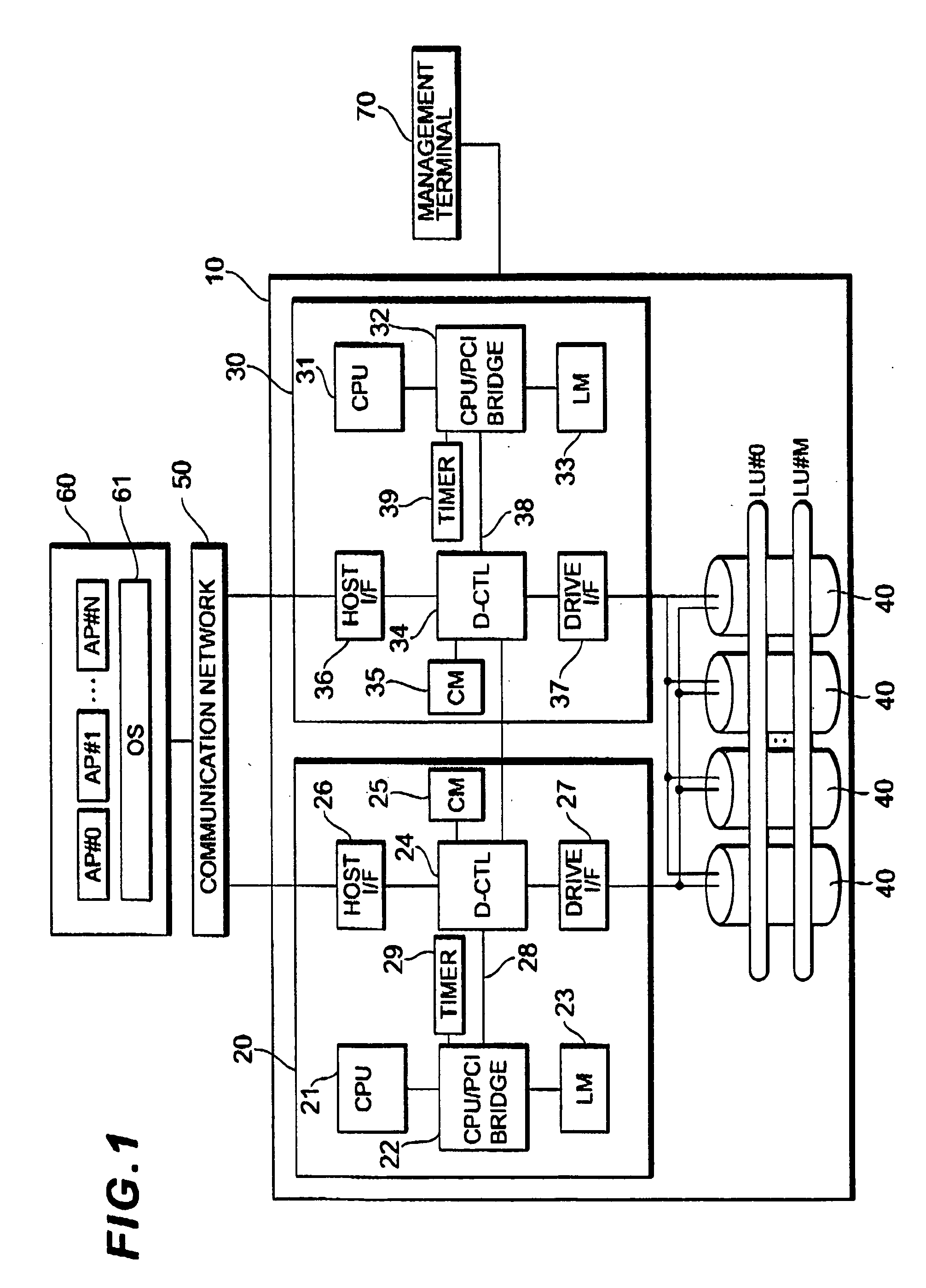
[0042]FIG. 1 shows a main configuration of the storage system according to the present embodiment.

[0043] A storage system 10 is connected to one or a plurality of host devices 60 via a communication network 50. The host device 60 is a server device, personal computer, workstation, main frame, or the like which functions as a higher-level device of the storage system 10. The host device 60 has mounted therein a plurality of application programs AP#0, AP#1, . . . , AP#N that are operated on an OS (operating System) 61. A storage resource provided by the storage system 10 is shared by the plurality of application programs AP#0, AP#1, . . . , AP#N.

[0044] Examples of the communication network 50 include, for example, a SAN (Storage Area Network), LAN (Local Area Network), Internet, dedicated circuit, public circuit, and the like. When the host device 60 is connected to the storage system 10 via a SAN, the host device 60 requests data input / output by a block which is a data executive un...

embodiment 2

[0119]FIG. 21 shows a main configuration of the storage system according to the present embodiment. Since the hardware with the same symbols as those shown in FIG. 1 indicate the same hardware, the detailed explanations are omitted.

[0120] The local memory 23 is provided with, in addition to the program region 23b which stores the micro program of the CPU 21, a management in formation region 23a for store management information required in management of the user data, such as data attributes (read data / write data), a logical address of the user data, which is specified by the host device 60, free area information on the cache memory, and information of the priority related to the cache data replacement. On the other hand, although the cache memory 25 is provided with the user data region 25b for temporarily storing the user data (cache data), it is not provided with the management information region for managing the user data.

[0121] When a write access is made from the host device ...

embodiment 3

[0123]FIG. 22 shows a main configuration of the storage system according to the present embodiment. Since the hardware with the same symbols as those shown in FIG. 1 or FIG. 21 indicate the same hardware, the detailed explanations are omitted.

[0124] The local memory 23 and the cache memory 25 are respectively provided with the management information region 23a, 25a for storing the management information of the cache data, wherein binary management information is managed. The CPU 21 refers to the management information region 23a of the local memory 23 with regard to a write access or read access from the host device 60, thereby searching a free area in the user data region 25b or performing cache hit judgment. One the CPU 21 writes the write data into the free area of the user data region 25b with regard to the write access from the host device 60, the CPU 21 updates the management information stored in both the management information regions 23a, 25a. Updating the management infor...


PUM


Abstract

An object of the present invention is to provide a storage system which is shared by a plurality of application programs, wherein optimum performance tuning for a cache memory can be performed for each of the individual application programs. The storage system of the present invention comprises a storage device which provides a plurality of logical volumes which can be accessed from a plurality of application programs, a controller for controlling input and output of data to and from the logical volumes in response to input / output requests from the plurality of application programs, and a cache memory for temporarily storing data input to and output from the logical volume, wherein the cache memory is logically divided into a plurality of partitions which are exclusively assigned to the plurality of logical volumes respectively.

Description

CROSS-REFERENCES TO RELATED APPLICATIONS [0001] This application relates to and claims priority from Japanese Patent Application No. 2005-037347, filed on Feb. 15, 2005, the entire disclosure of which is incorporated here in reference. BACKGROUND OF THE INVENTION [0002] 1. Field of the Invention [0003] The present invention relates to a storage system which can optimize performance tuning of a cache memory for each of a plurality of application programs. [0004] 2. Description of the Related Art [0005] Recently, storage consolidation where storages dispersed in each server are consolidated in a single place and connected to servers via a storage-dedicated network such as a SAN (Storage Area Network) has been widely used. As an operation pattern of the storage consolidation, common use of a storage system by a plurality of application programs or contents has been increasing. The storage system is configured with, for example, a disk array device and the like. A disk array device is c...

Claims


Application Information

Patent Timeline
Patent Type & Authority Applications(United States)
IPC IPC(8): G06F12/00
CPCG06F12/084G06F12/121G06F12/0875G06F2212/282G06F12/0873G06F2212/261
Inventor ISHIKAWA, ATUSHIMATSUI, YUKO
Owner HITACHI LTD
Why Eureka
Try Eureka