Multi-eye imaging apparatus

a multi-eye, imaging apparatus technology, applied in the field of multi-eye imaging apparatus, can solve the problems of unavoidably long apparatus, poor resolution, thick imaging apparatus, etc., and achieve the effect of preventing a reduction in the effect of pixel shi

Inactive Publication Date: 2007-07-12
PANASONIC CORP
View PDF14 Cites 49 Cited by
  • Summary
  • Abstract
  • Description
  • Claims
  • Application Information

AI Technical Summary

Benefits of technology

[0024] The present invention is intended to solve conventional problems, such as those described above. An object of the present invention is to provide a multi-eye imaging apparatus of performing pixel shift that is capable of preventing a reduction in the effect of pixel shift even when there is an apparatus shake or a subject shake.

Problems solved by technology

In this structure, the optical system of the imaging apparatus is unavoidably long, so that the imaging apparatus is thick.
Therefore, the resolution is poor, compared to typical imaging apparatuses having a Bayer array in which green, red and blue filters are arranged in a staggered pattern.
Therefore, if images that should interpolate each other are deviated from each other, the resolution may be deteriorated.
However, in the case of the fixing method of using a tripod or the like, for example, it is necessary for the user to always carry the tripod, so that the convenience for the user is significantly deteriorated, i.e., the method is not practical.
In the case of the methods of Patent Documents 2 and 3 in which an apparatus shake is detected using a sensor to perform apparatus shake correction and pixel shift, the sensor is newly required, a complicated optical system is required, and the like, which are disadvantageous to the reduction of size and thickness.
However, it is expected that an image is positioned appropriately by chance due to an apparatus shake or the like, so that the resolution is not reliably improved.

Method used


Image

  • Multi-eye imaging apparatus
  • Multi-eye imaging apparatus
  • Multi-eye imaging apparatus

Examples


embodiment 1

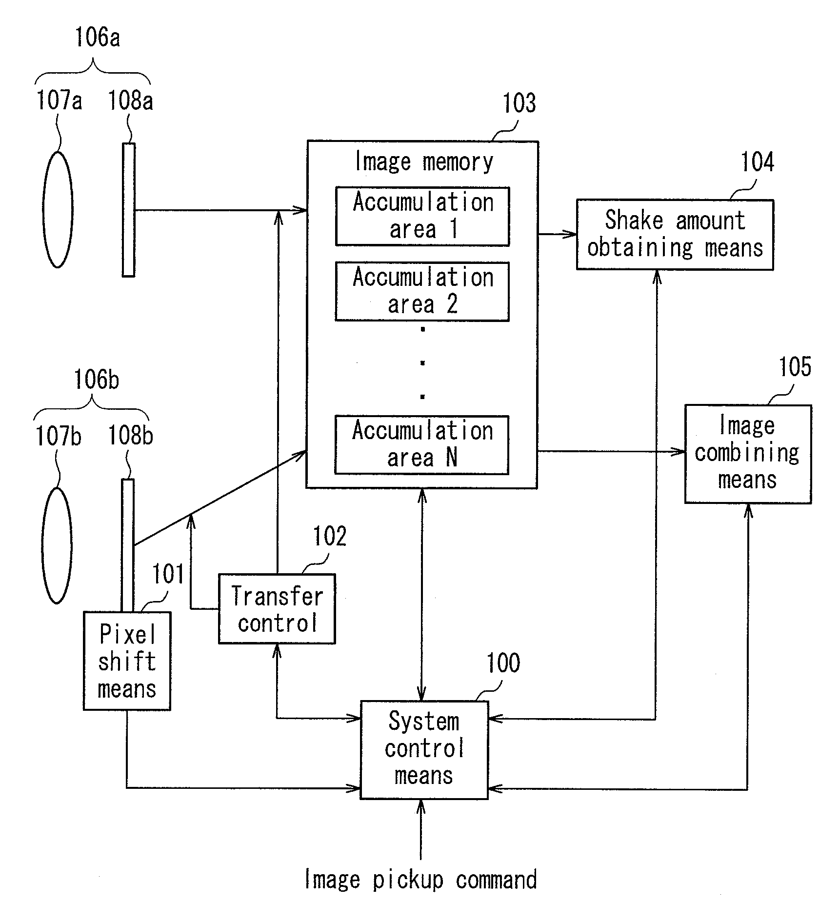
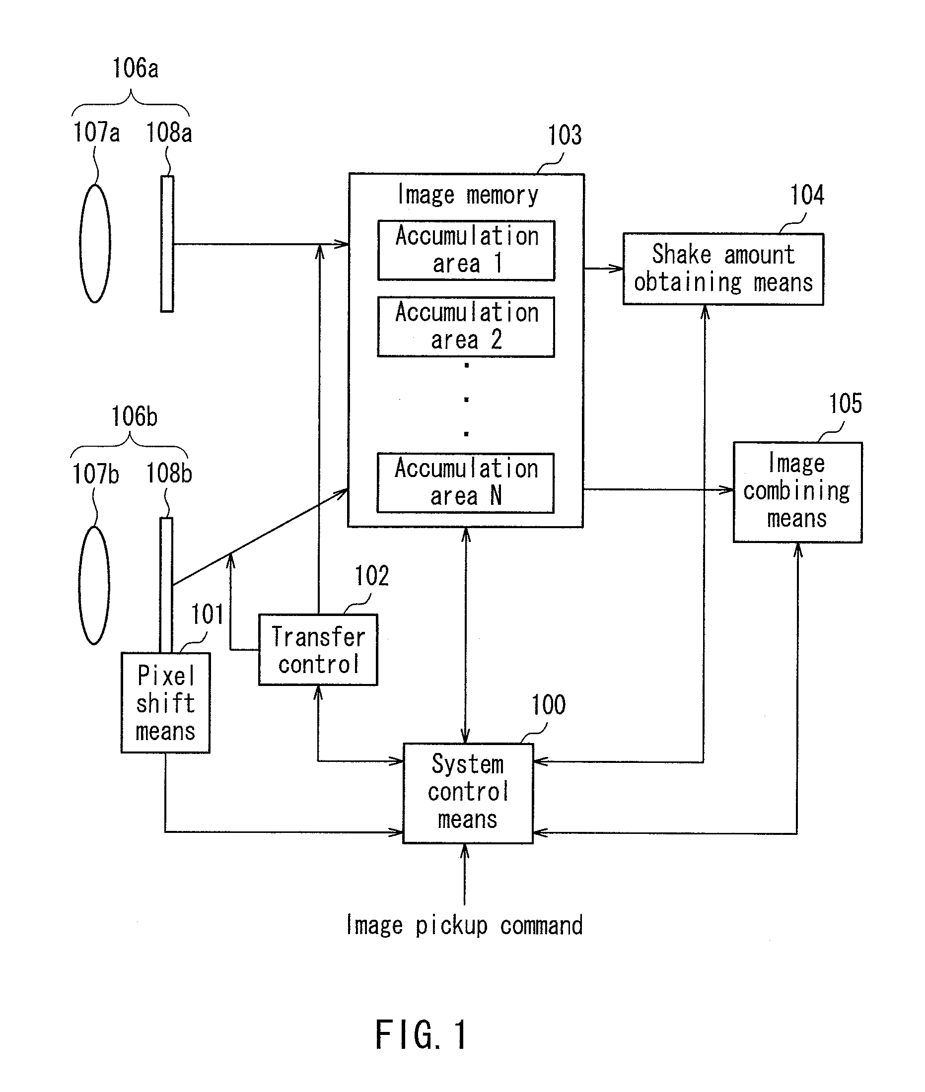
[0056]FIG. 1 is a block diagram illustrating a configuration of an imaging apparatus according to Embodiment 1. A system control means 100 is a Central Processing Unit (CPU) which controls the whole imaging apparatus. The system control means 100 controls a pixel shift means 101, a transfer means 102, an image memory 103, a shake amount obtaining means 104, and an image combining means 105.

[0057] An image of a subject (not shown) to be captured is captured using a first imaging system 106b that has the pixel shift means 101 and a second imaging system 106a that does not have a pixel shift function. The subject is imaged on imaging elements 108a and 108b using an imaging optical system 107a and an imaging optical system 107b, and is converted into image information as a light intensity distribution.

[0058] The pixel shift means 101 shifts a relative positional relationship between the subject image formed on the imaging element 108b by the imaging optical system 107b, and the imagin...

example 1

[0097]FIG. 6 illustrates a configuration of an imaging optical system, a pixel shift means, and an imaging element, according to Example 1. As the imaging optical system, two aspherical lenses 601a and 601b each having a diameter of 2.2 mm were used. The lenses were assumed to have optical axes that are substantially parallel to a Z axis in FIG. 6 and have an interval of 3 mm.

[0098] A first imaging system that performs pixel shift was provided with a glass plate 602 on the optical axis of the lens 601b. The glass plate 602 can be tilted with respect to an X axis and a Y axis using a piezoelectric actuator and a tilting mechanism (not shown). In this example, pixel shift was performed by ½ (1.2 μm) of a pixel pitch in a horizontal direction (X-axis direction), thereby doubling the number of pixels. As the glass plate 602, BK7 was used, which is an optical glass having a width (X-axis direction) of 2 mm, a height (Y-axis direction) of 2 mm, and a thickness (Z axis direction) of 500 μ...

embodiment 2

[0103]FIG. 7 illustrates a configuration of an imaging apparatus according to Embodiment 2. Embodiment 2 is different from Embodiment 1 mainly in that a parallax amount obtaining means 700 is added, an imaging element 701 is formed integrally, image capture is performed by a first imaging system and a second imaging system at substantially the same time, and an optimal image selecting means 702 for selecting images to be combined, based on a parallax amount and a shake amount, is added. Portions overlapping Embodiment 1 will not be described.

[0104]FIG. 8 illustrates a flowchart of the whole operation of the imaging apparatus of this embodiment. An imaging start command in step 200 and an image capture preprocess in step 201 are similar to those of Embodiment 1.

[0105] In step 800, image capture is performed using pixel shift. In step 800, a process of exposing the imaging element (step 801), a process of transferring an image of the imaging element to the image memory 103 (step 802...


PUM


Abstract

A multi-eye imaging apparatus comprises a plurality of imaging systems (106a, 106b) each including an optical system (107a, 107b) and an imaging element (108a, 108b) and having a different optical axis. The plurality of imaging systems (106a, 106b) include a first imaging system (106b) having a pixel shift means (101) for changing a relative positional relationship between an image formed on the imaging element (108b), and the imaging element (108b), and a second imaging system (106a) in which a relative positional relationship between an image formed on the imaging element (108a), and the imaging element (108a), is fixed during time-series image capture.

Description

TECHNICAL FIELD [0001] The present invention relates to a multi-eye imaging apparatus having a pixel shift function. BACKGROUND ART [0002] Imaging apparatuses for use in mobile apparatuses need to have both a high resolution and a small size. A reduction in size of the imaging apparatus is limited by the size and focal length of an imaging optical lens and the size of an imaging element. [0003] In general, since the index of refraction is different depending on the wavelength of light, a scene including information of all wavelengths cannot be imaged on an image capture surface using a single lens. Therefore, typical imaging apparatuses have an optical system composed of a plurality of lenses superposed together so that light having red, green and blue wavelengths are imaged on the same imaging surface. In this structure, the optical system of the imaging apparatus is unavoidably long, so that the imaging apparatus is thick. Therefore, a multi-eye type imaging apparatus including si...

Claims


Application Information

Patent Timeline
Patent Type & Authority Applications(United States)
IPC IPC(8): H04N5/225G06T3/00H04N5/232H04N5/349H04N9/09
CPCH04N5/2254H04N9/097H04N9/045H04N5/2259H04N23/58H04N23/16H04N23/843
Inventor KUMAGAI, HIRONORIHIRASAWA, TAKU
Owner PANASONIC CORP
Why Eureka
Try Eureka