
Material feeding device, recording device and liquid injecting device

A feeding device and liquid technology, applied in printing devices, thin material handling, transportation and packaging, etc., can solve problems such as cost increase, difficulty in component precision management, and long feeding roller shaft

Inactive Publication Date: 2007-12-19
SEIKO EPSON CORP
View PDF1 Cites 5 Cited by
  • Summary
  • Abstract
  • Description
  • Claims
  • Application Information

AI Technical Summary

Problems solved by technology

[0010] However, in the case where the feed auxiliary roller 510 is installed on the 80th place side, it is necessary to extend the feed roller shaft (not shown) to the 80th place side.
Therefore, precision management of parts becomes difficult
In addition, the shaft of the feed roller is long, which may increase the cost

Method used


Image

  • Material feeding device, recording device and liquid injecting device
  • Material feeding device, recording device and liquid injecting device
  • Material feeding device, recording device and liquid injecting device

Examples


Embodiment approach

[0084] 6 and 7 are perspective views showing feeding devices according to other embodiments. Among them, FIG. 6 is a diagram showing no CD-R tray, and FIG. 7 is a diagram showing a CD-R tray.

[0085] As shown in FIG. 6 , the flat portion 318 of the second guide portion 111 is disposed at the same height and parallel to the upper surface of the platen 124 , and is extended further upstream in the above-mentioned embodiment. Furthermore, the retracting guide portion 117 of the second guide portion 111 is provided with a tray opening portion 319 through which the CD-R tray Q having the flat portion 318 as a lower surface can be inserted.

[0086] In addition, a discharge unit 320 for discharging paper P is provided on the front of the recording device 100 (on the front side in FIGS. 6 and 7 ). In addition, a discharge opening 321 for discharging the paper P from the inside of the recording device 100 to the outside is provided in the discharge unit 320 . For other members, sin...

other Embodiment approach

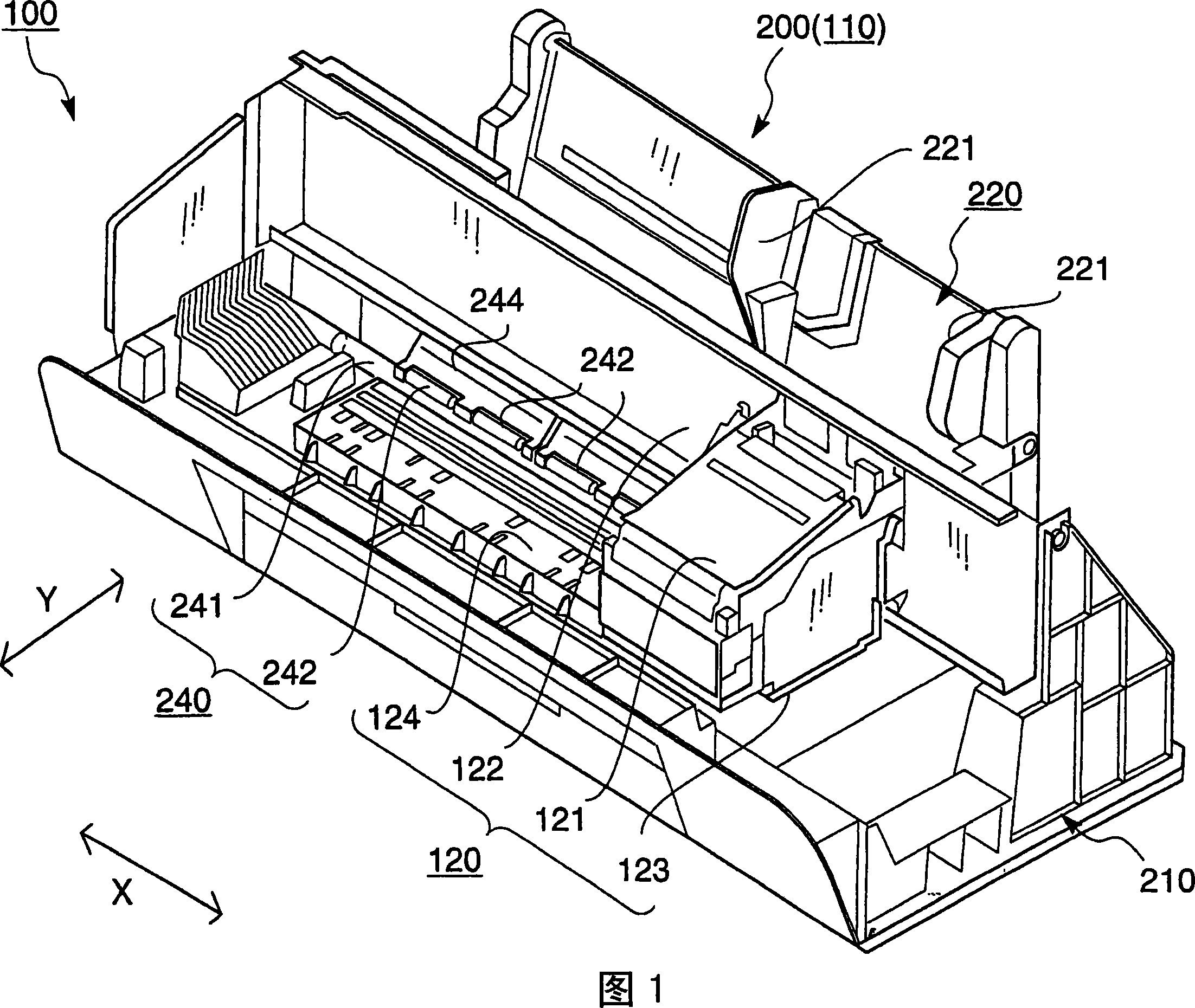
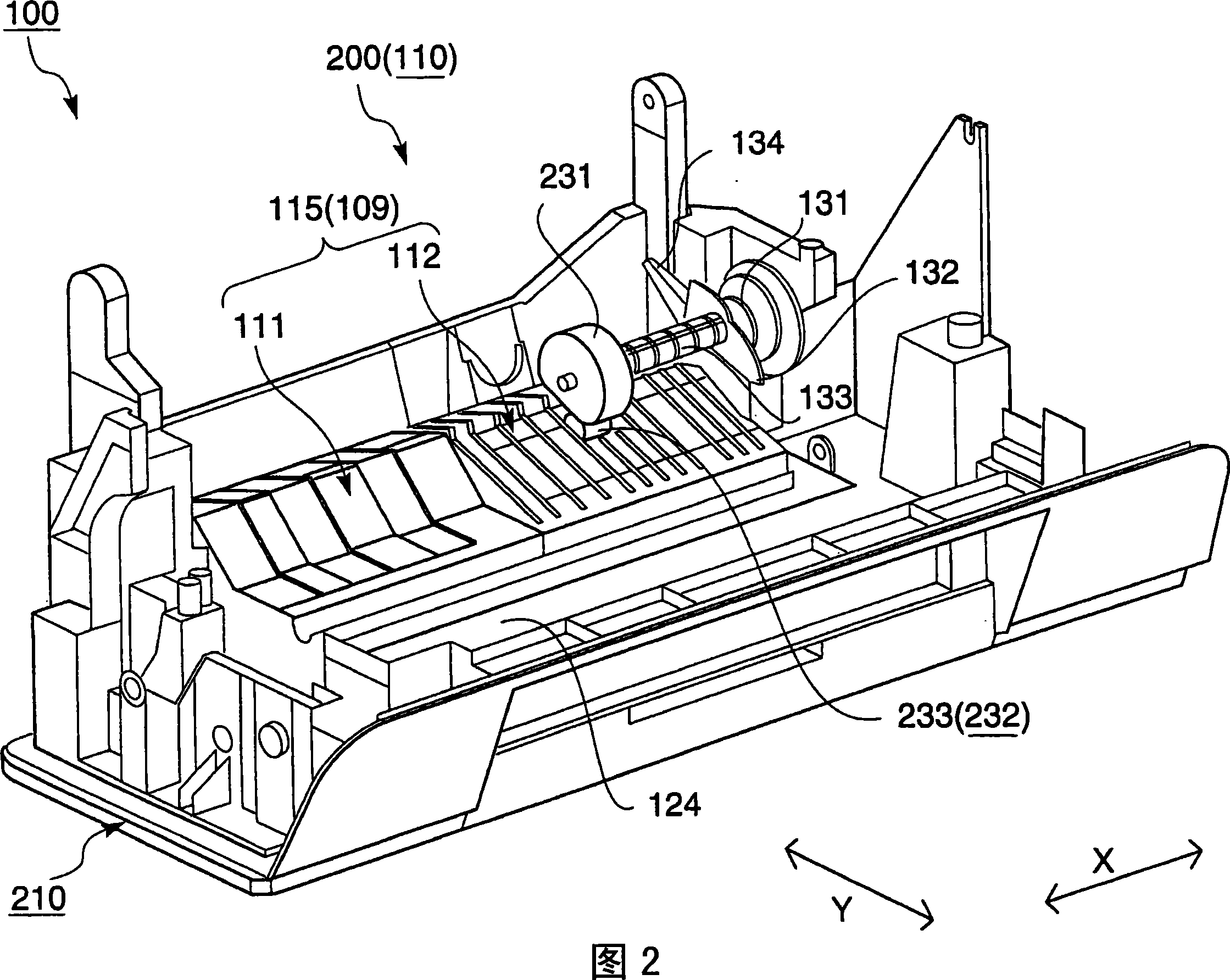
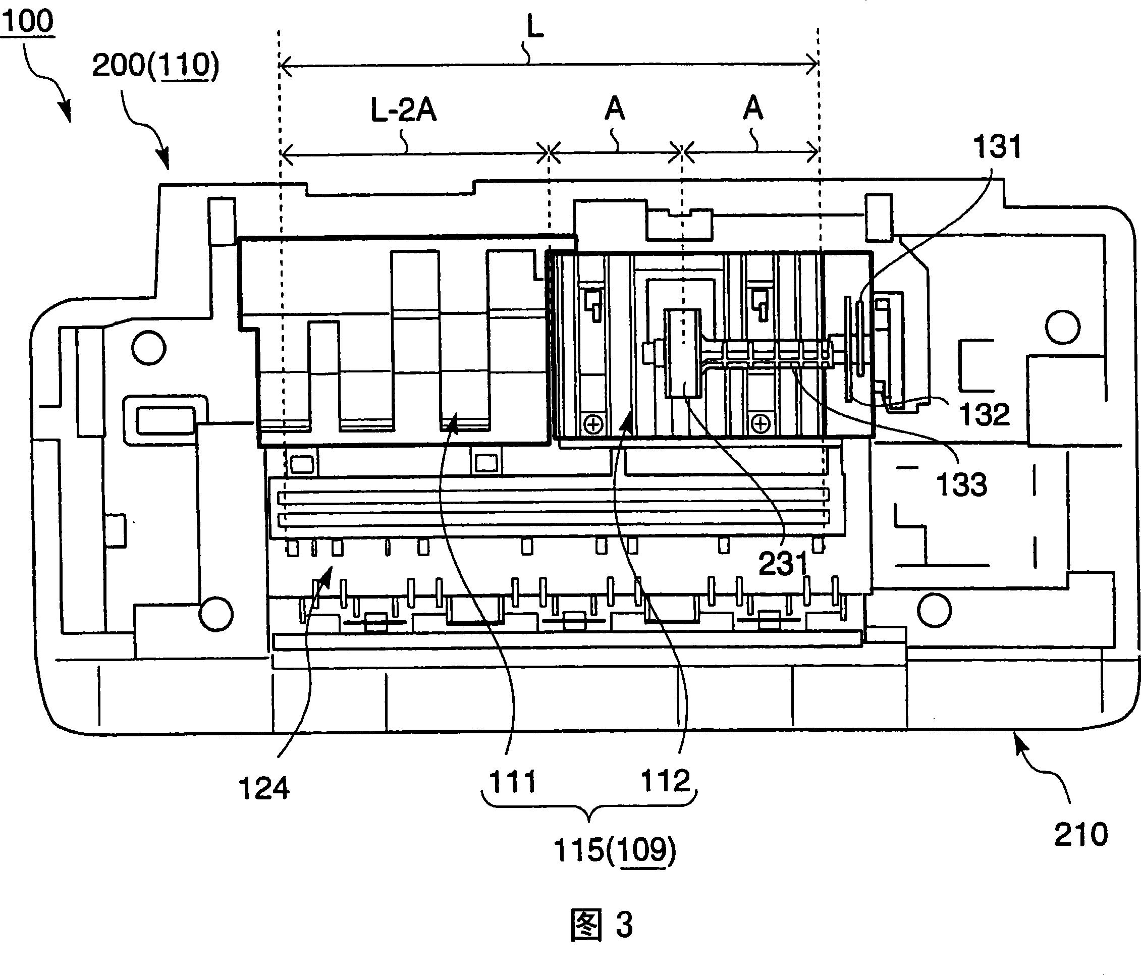
[0089] The second guide section 111 of another embodiment is characterized in that it includes a flat section 318 that not only retracts downward relative to the first guide section 112 to guide the paper P toward the conveying roller pair 240 , but also guides the sheet P as only during the main scanning. The CD-R tray Q of the second medium that performs recording within the range of the second guide section 111 in the direction X, the CD-R tray Q is set so that it is only moved in the main scanning direction of the paper guide section 115 as a medium guide section. The flat portion 318 supports and guides from below.

other Embodiment approach

[0090] The recording device 100 of another embodiment includes: a feeding unit 110 that picks up stacked paper P and supplies it to the recording unit side; and a recording unit that ejects ink to the paper P and CD-R (Q) to perform recording. 120, characterized in that the feeding unit 110 is equipped with the above-mentioned feeding device 200.


PUM


Abstract

The present invention provides a material feeding device, a recording device and a liquid jetting device. In the material feeding device, the feeding roller picks the stacked first medium and feeds it to the downstream side. The medium guiding part guides the feeding first medium. The feeding roller pair conveys the guided first medium. The feeding roller is arranged at the off-center side relative to the medium guiding part at the breadth direction of the feeding first medium, namely the main scanning direction. The medium guiding part is provided with a first guiding part which is arrayed in the main scanning direction and a second guiding part which guides the path of the first medium and is different from the first guiding part. The first guiding part is arranged at the offset side of the feeding roller in the main scanning direction. The second guiding part is arranged at the other side in the main scanning direction.

Description

technical field [0001] The present invention relates to a feed roller that picks up a stacked first medium and supplies it to the downstream side, a medium guide section that guides the supplied first medium to a delivery roller, and transports the guided first medium to a recording section. The feeding device of the conveying roller pair is provided with a recording device and a liquid ejecting device of the feeding device. Background technique [0002] Here, the liquid ejecting device refers not only to recording devices such as inkjet recording devices, copiers, and facsimiles that eject ink from a recording head that is a liquid ejecting head to a recording material such as recording paper, thereby performing recording on the recording material, but also includes recording devices from The liquid ejection head corresponding to the above-mentioned recording head is a device for ejecting a liquid corresponding to a specific application instead of ink to the ejected materia...

Claims


Application Information

Patent Timeline
Patent Type & Authority Applications(China)
IPC IPC(8): B41J13/02B41J13/26B65H3/06B65H9/00
CPCB65H3/0661B65H2404/52131B65H2404/5211B65H2404/1411B65H2404/51B65H2601/272
Inventor 中岛洋生
Owner SEIKO EPSON CORP
Learn More