Humidity adjusting device

A technology of humidity adjustment and adsorption heat exchanger, which is applied in the direction of air conditioning system, ventilation system, heating method, etc. It can solve the problems of increased pressure loss, sudden change of air, and easy complication of air circulation path, so as to restrain the direction of air flow The change of the pressure loss and the effect of reducing the pressure loss

Inactive Publication Date: 2012-01-04
DAIKIN IND LTD
View PDF1 Cites 0 Cited by
  • Summary
  • Abstract
  • Description
  • Claims
  • Application Information

AI Technical Summary

Problems solved by technology

[0006] As described above, in the humidity control device disclosed in Patent Document 1, it is necessary to make the two kinds of air (outdoor air and indoor air) flow in the housing without mixing with each other, and it is also necessary to control the circulation paths of the above two kinds of air. Switching, so the air circulation path in the housing is easily complicated
Moreover, if the air circulation path in the casing becomes complicated, the flow direction of the air in the casing will suddenly change, which may increase the pressure loss when the air passes through the casing.

Method used


Image

  • Humidity adjusting device
  • Humidity adjusting device
  • Humidity adjusting device

Examples


Embodiment Construction

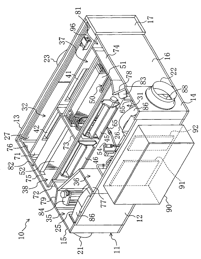
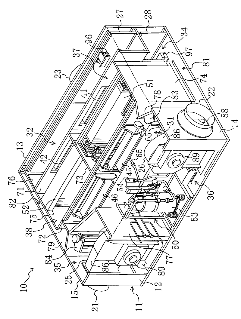
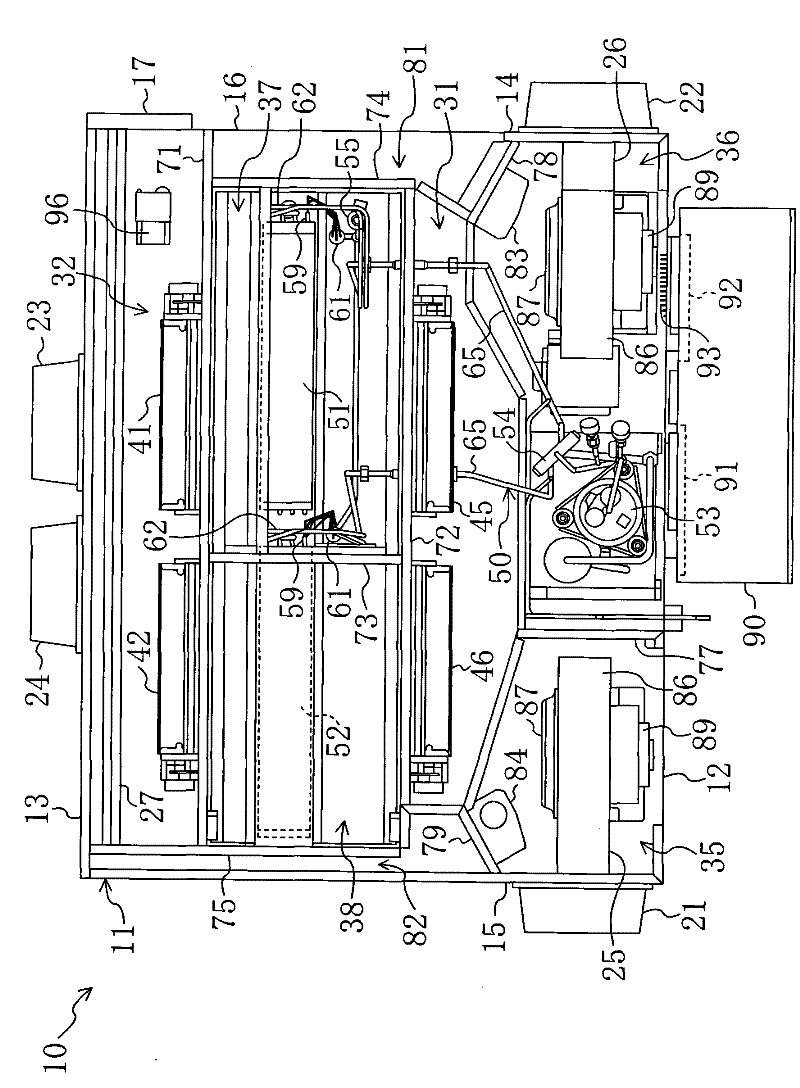
[0023] Hereinafter, embodiments of the present invention will be described in detail with reference to the drawings. The humidity control device 10 of this embodiment is a device that ventilates the room while adjusting the indoor humidity. It adjusts the humidity of the outdoor air OA sucked in, supplies the outdoor air OA into the room, and simultaneously ventilates the sucked indoor air. The air RA is exhausted to the outside.

[0024] (The overall structure of the humidity control device) While referring to Figure 1 to Figure 6 , the humidity control device 10 will be described. In addition, as long as there is no special notice, "up", "down", "left", "right", "front", "rear", "near", and "far" used in the description here refer to the The positional relationship when the humidity control device 10 is viewed from the front side.

[0025] The humidity control device 10 includes a housing 11 . In addition, a refrigerant circuit 50 is housed in the casing 11 . The refri...


PUM


Abstract

The invention discloses a humidity adjusting device. In a casing (11) of a humidity adjusting device (10), a first heat exchanger chamber (37) for receiving a first adsorption heat exchanger (51) and a second heat exchanger chamber (38) for receiving a second adsorption heat exchanger (52) are formed next to each other in the left-right direction. An inside air-side path (32) and an outside air-side path (34) are formed on the rear panel (13) sides of the heat exchanger chambers (37, 38), and an air supply-side path (31) and an air discharge-side path (33) are formed on the front panel (12) sides of the heat exchanger chambers (37, 38). An outside air suction opening (24) and an inside air suction opening (23) are formed to lie to the center in the lateral (left and right) direction of the rear panel (12). An air supply opening (22) is formed to lie to the front of a first side panel (14), and an air discharge opening (21) is formed to lie to the front of a second side panel (15). An air supply fan (26) is connected to the air supply opening (22), and an air discharge fan (25) is connected to the air discharge opening (21). A pressure loss when air passes through inside the casingis suppressed to a low level.

Description

technical field [0001] The invention relates to a humidity adjusting device which uses an adsorbent to adjust air humidity. Background technique [0002] Hitherto, humidity control devices that use adsorbents to control air humidity are known. In Patent Document 1, a humidity control device including an adsorption heat exchanger having an adsorbent carried on its surface is disclosed. [0003] In the humidity control device disclosed in Patent Document 1, a refrigerant circuit including two adsorption heat exchangers is provided. In this refrigerant circuit, an operation in which the first adsorption heat exchanger functions as a condenser and a second adsorption heat exchanger functions as an evaporator and an operation in which the second adsorption heat exchanger functions as a condenser and the first adsorption heat exchanger functions as an evaporator are alternately performed. In an adsorption heat exchanger operating as an evaporator, the moisture in the air is abso...

Claims


Application Information

Patent Timeline
Patent Type & Authority Patents(China)
IPC IPC(8): F24F3/147
CPCF24F3/1411F24F3/1429F24F11/0008F24F3/147F24F7/08
Inventor 成川嘉则池上周司松井伸树
Owner DAIKIN IND LTD
Why Eureka
Try Eureka