Radio wave route loss simulation measuring method

A path loss, radio wave technology, used in electrical components, transmission monitoring, transmission systems, etc., can solve problems such as design without time complexity and space complexity, and no mention of accuracy/speed ratio.

Active Publication Date: 2007-12-19
ZTE CORP
View PDF2 Cites 19 Cited by
  • Summary
  • Abstract
  • Description
  • Claims
  • Application Information

AI Technical Summary

Problems solved by technology

The main purpose of this patent is how to establish a wireless network planning tool, which involves the calcula

Method used


Image

  • Radio wave route loss simulation measuring method
  • Radio wave route loss simulation measuring method
  • Radio wave route loss simulation measuring method

Examples


Embodiment Construction

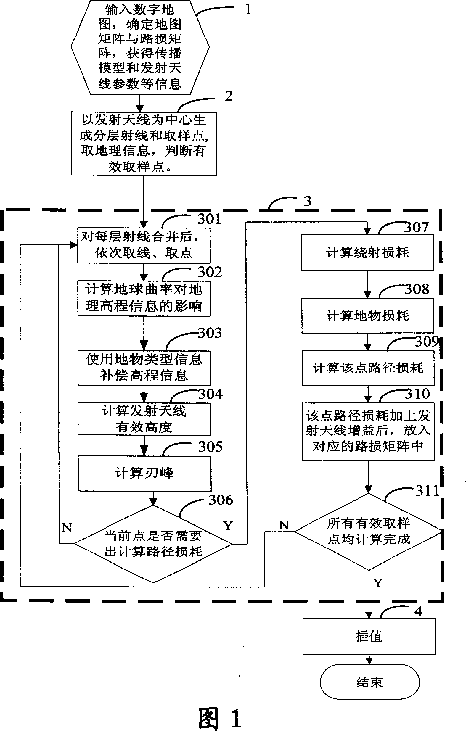
[0038] As shown in Fig. 1, the method of the present invention is further described by taking a specific network as an example.

[0039] Step 1. Input information such as digital map, propagation model, transmitting antenna parameters, receiving antenna parameters and earth radius. A map matrix is ​​generated from the digital map, and a path matrix is ​​generated from the predicted radius.

[0040] In this embodiment, the network includes a transmitting antenna and adopts the COSTT231-Hata propagation model. The downtilt angles are all θ degrees. The accuracy of the digital map is 20 meters, and the map includes elevation information and ground object information. Take the virtual earth radius a=4r / 3=8493km.

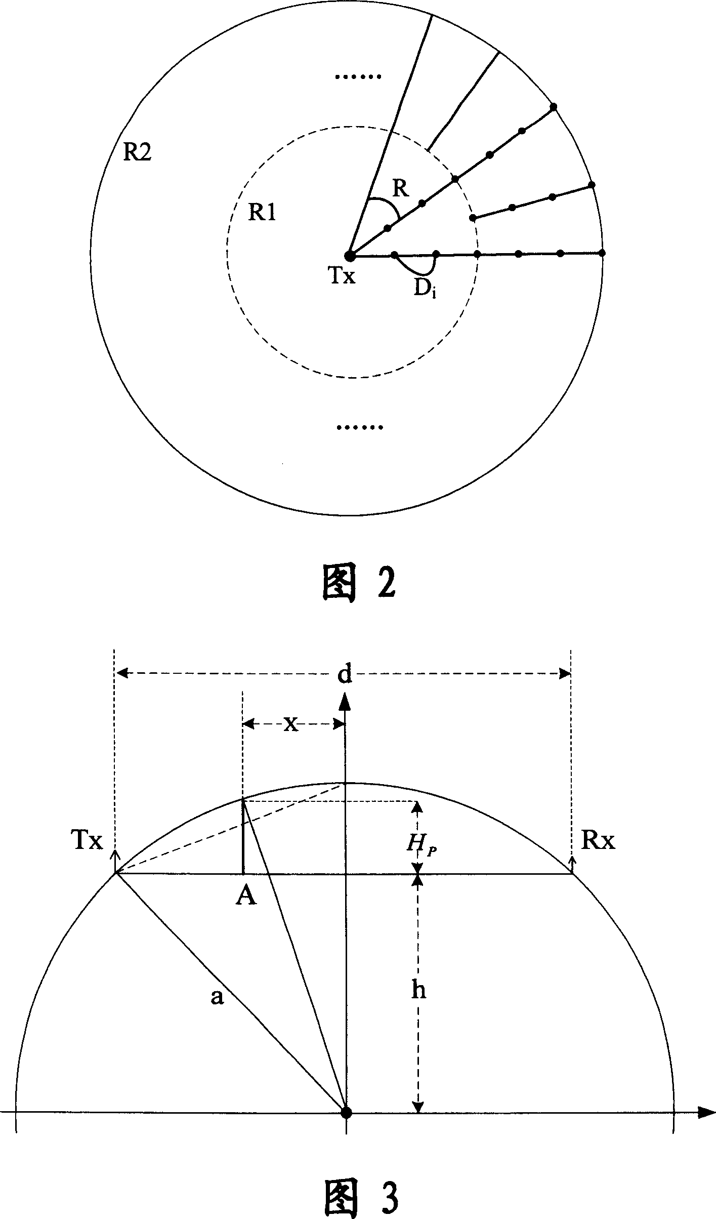
[0041] Step 2, according to the parameters of the transmitting antenna and the range to be measured, generate a series of layered rays starting from the transmitting antenna, take a series of sampling points on each ray, and according to the position corresponding to ...


PUM


Abstract

This invention discloses a simulation measuring method for path loss of radio waves including: inputting a digital map, determining a map matrix and a loss matrix to get a spread model and parameter of an emission antenna, generating a series of lamination radials with the emission antenna as the starting point, taking a series of sampling points on each radial and determining the effective sampling points according to the map grids corresponding to the sample point positions in the map matrix, then computing the effective height of the antenna and diffraction loss according to the corresponding geographical information of the effective sampling points and computing the path loss of the effective sampling point to be taken as the path loss of the map grids corresponding to the effective sampling points to be stored in the path loss matrix.

Description

technical field [0001] The invention relates to wireless communication technology and provides a fast and effective method for measuring path loss in radio waves. Background technique [0002] The quality of wireless network planning and design directly affects various indicators of mobile communication networks, and the complexity of radio wave propagation greatly increases the uncertainty of wireless network planning quality. Simulating the real network environment through simulation software and simulating network performance is an effective means to improve the quality of network planning. [0003] The confidence of the simulation depends heavily on the accuracy of the path loss calculation. The propagation of radio waves in a realistic propagation environment is affected by complex terrain and features, and there are multiple propagation paths such as direct radiation, reflection, diffraction, and scattering, which lead to very complicated path loss calculations. For ...

Claims


Application Information

Patent Timeline
IPC IPC(8): H04B17/00H04B7/005
Inventor 欧阳俊吴峰李晟陈健
Owner ZTE CORP
Why Eureka
Try Eureka