

Electronical jumpering table of radio frequency identification
An identification and wiring table technology, applied in the field of radio frequency identification, can solve problems such as ambiguity, hidden dangers in maintenance, damaged handwriting, etc., to achieve the effect of convenient sharing of information and not easy to damage
- Summary
- Abstract
- Description
- Claims
- Application Information
AI Technical Summary
Problems solved by technology
Method used
Image

Examples
Embodiment Construction
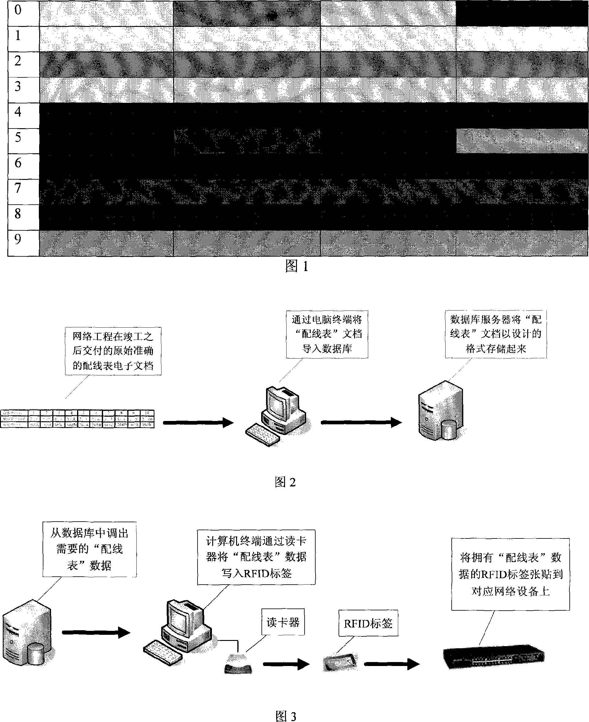
[0038] Embodiments of the present invention are illustrated below.
[0039] 1) The port number information of the distribution frame is 3 rows and 14 columns, and 3×24+14=86 is obtained, and the number 86 is obtained.
[0040] 2) The port downlink device information is the network port module, the corresponding number is 1, and the number 1 is obtained.
[0041] 3) After the above two values are recompressed, 86×8+1=689 is obtained, and the value 0689 is obtained by padding less than 4 digits with zeros.
[0042] 4) The location area information is the teaching administration building, and the corresponding number is 98. If there are less than 3 digits, add 0 in front to get the number 098.
[0043] 5) The location cell information is a conference room, and the corresponding number is 8, and the number 08 is obtained by adding 0 in front of less than 2 digits.
[0044] 6) The module position information is 15 rows and 40 columns, which results in 15×50+40=790, if less than...
PUM
 Abstract
Description
Claims
Application Information