
Optical signal transmitter and optical wireless communications network using it

An optical signal and optical wireless technology, applied in electromagnetic transmitters, data exchange through path configuration, electromagnetic wave transmission systems, etc., can solve the problem of increased installation costs, increased production costs of optical signal transmitters and receivers, and difficulty in providing standardization Optical wireless communication services and other issues

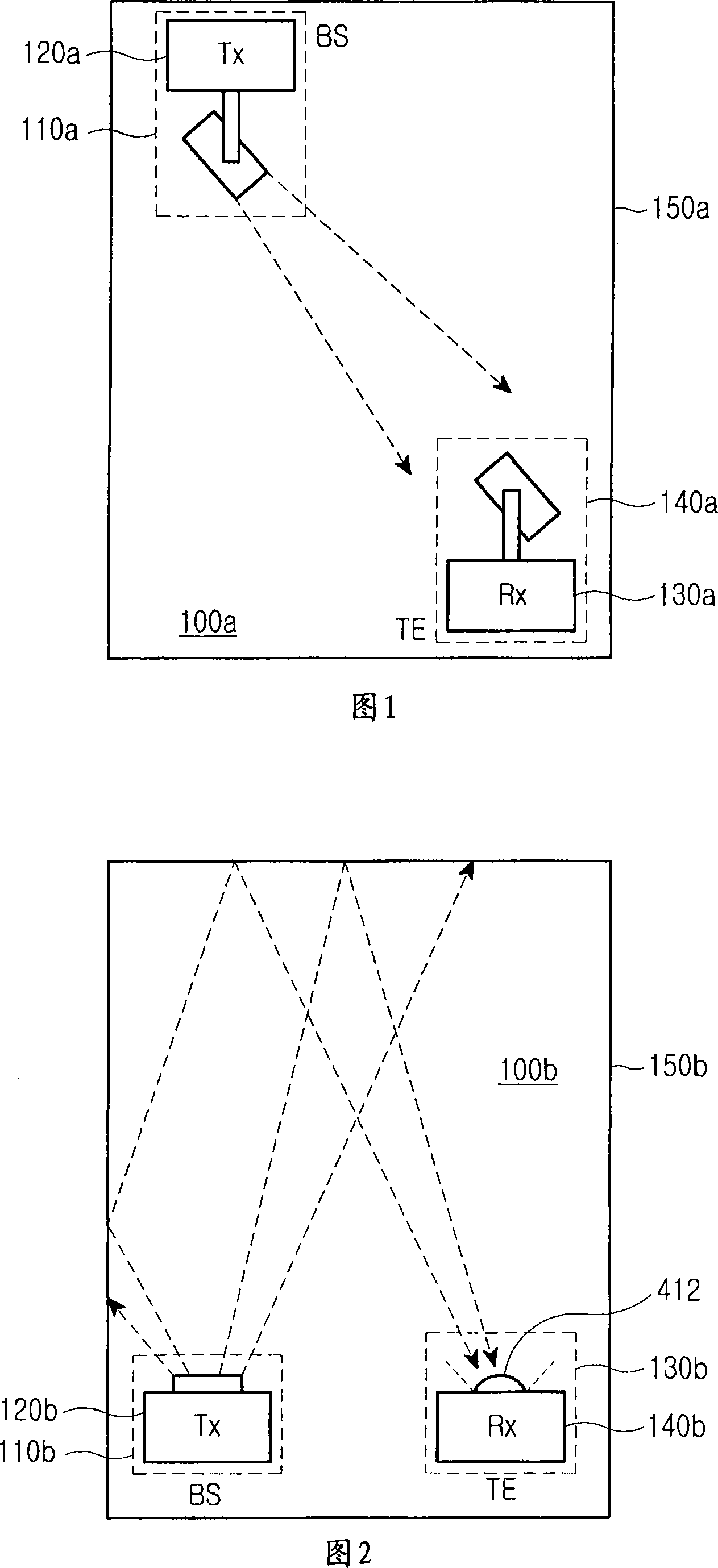
Inactive Publication Date: 2007-12-26
SAMSUNG ELECTRONICS CO LTD +1
View PDF0 Cites 6 Cited by
  • Summary
  • Abstract
  • Description
  • Claims
  • Application Information

AI Technical Summary

Problems solved by technology

However, this configuration has the disadvantage that objects traversing or moving within the communication path can disrupt LOS connectivity
[0010] First, when the position of the ceiling and walls and the interior space of the building change with the height and area of ​​the ceiling, it is difficult to provide standardized optical wireless communication services other than customizing the service according to the given building environment
Therefore, the role of field engineers is important, which leads to increased installation costs, and the difficulty of standardizing optical wireless communication services increases the production costs of optical signal transmitters and receivers
[0011] Second, ISI limits the communication speed because scattered optical signal components, each with a large path difference, are transmitted to the optical signal receiver
[0012] Third, the optical signal transmitter must have a high power output to compensate for the low power caused by the scattering of the optical signal, again increasing production costs
[0013] Fourth, only the downlink for sending optical signals from the base station to the terminal is considered

Method used


Image

  • Optical signal transmitter and optical wireless communications network using it
  • Optical signal transmitter and optical wireless communications network using it
  • Optical signal transmitter and optical wireless communications network using it

Examples


Embodiment Construction

[0034] Exemplary embodiments of the present invention will be described herein below with reference to the accompanying drawings. In the drawings, the same or similar elements are denoted by the same reference numerals even if they are shown in different drawings. For the purpose of clarity and conciseness, well-known functions or constructions are not described in detail since such details would obscure the invention in unnecessary detail.

[0035] In order to enable optical wireless communication in each communication cell having their respective base stations, the optical wireless communication network of the present invention connects a plurality of communication cells defined by dividing local communication areas. In order to selectively illuminate the corresponding cells, each base station includes at least a directional optical signal transmitter. The optical signal transmitters of the present invention are all directional, and are classified into a plurality of types ...


PUM


Abstract

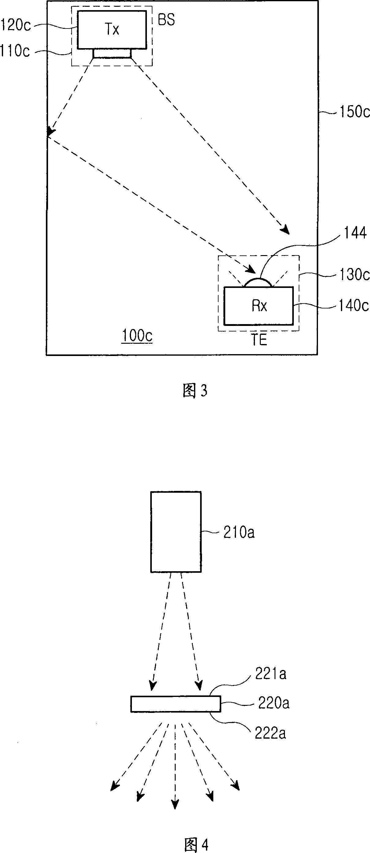
An optical wireless communications network connects a plurality of communication cells, which are defined by dividing a local communication area, for enabling optical wireless communication in each of the communication cells. An optical signal transmitter is installed in each communication cell for irradiating the cell with a data-modulated optical signal to perform data transmission to a terminal located therein. The optical signal transmitter comprises an optical signal source for outputting the data-modulated optical signal, and an optical signal diffuser with a concave inside surface facing the output end of the optical signal source for diffusing and reflecting the data-modulated optical signal to irradiate the cell.

Description

technical field [0001] The present invention relates to optical wireless communication, and more particularly, to an optical transmitter / receiver capable of data communication by transmitting and receiving optical signals through free space. Background technique [0002] Generally, there are three ways to construct an optical wireless communication LAN (Local Area Network) capable of optical wireless communication in buildings: [0003] The first, LOS (Line of Sight) communication, requires a line of sight state between the base station (BS) and the terminal (TE), so that the base station sends optical signals directly to said terminal; [0004] The second, NLOS (non-line-of-sight) communication, in which base stations transmit optical signals towards walls and ceilings so that the optical signals can be reflected by them towards receiving terminals; and [0005] The third, hybrid communication, combines LOS and NLOS methods, in which the base station sends part of the opti...

Claims


Application Information

Patent Timeline
Patent Type & Authority Applications(China)
IPC IPC(8): H04B10/114H04B10/116H04L12/28
CPCH04B10/1149H04B10/116H04B10/11H04B10/50
Inventor 金昺稙黄星泽曹圭晚许亨晙权康赫
Owner SAMSUNG ELECTRONICS CO LTD
Learn More