
High resolution proton beam monitor

a monitor and proton beam technology, applied in the field of high-resolution proton beam monitors, can solve the problems of imposing containment and other difficulties, affecting the proton beam, and not being able to measure the angle and position of the exiting beam directly

Inactive Publication Date: 2007-08-09
LEXITEK
View PDF4 Cites 159 Cited by
  • Summary
  • Abstract
  • Description
  • Claims
  • Application Information

AI Technical Summary

Benefits of technology

[0012] In accordance with preferred embodiments of the present invention, an apparatus and method are provided for monitoring a spatial distribution, in a specified frame of reference, of a beam of penetrating radiation that traverses the apparatus en route to an irradiated object. The apparatus has a scintillator dispos...

Problems solved by technology

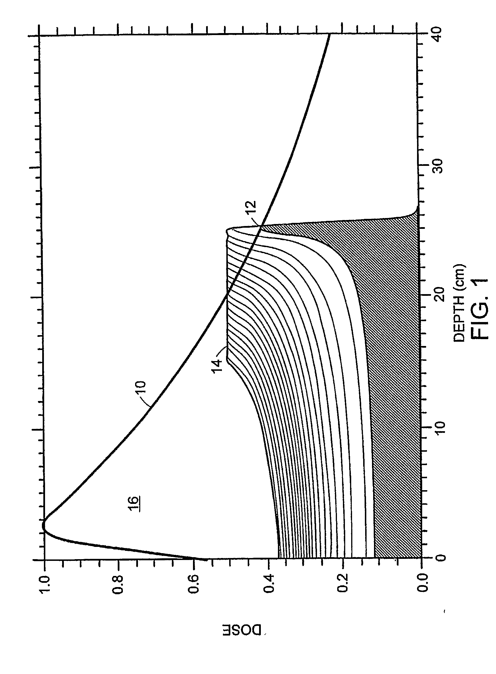
817-20 (1991)) for application to proton irradiation therapy, for monitoring overall beam intensity, and proving a real time feedback for beam intensity stabilization, however, the use of a gas scintillator imposes containment and other difficulties.
However, this current is not a direct measure of the exiting beam angle and position.
However, these are intrusive in that they significantly affect the proton beam and are of large complexity and thus cost.
Moreover, they may not stand up to the intense radiation for very long.
Various aspects of their performance, however, such as their scattering, spatio-temporal resolution, and their longevity and replacement cost after radiation damage, are less than desirable.

Method used


Image

  • High resolution proton beam monitor
  • High resolution proton beam monitor
  • High resolution proton beam monitor

Examples


Embodiment Construction

[0018] In accordance with preferred embodiments of the present invention, a beam of penetrating radiation is monitored with a scintillator. The term “penetrating radiation,” as used herein, and in any appended claims, refers both to particles with mass, such as protons, as well as to photons, i.e., to electromagnetic radiation such as x-rays or gamma rays. Moreover, in the case of massive particles, the particles are typically charged, such as protons or heavier atomic ions, however, neutrons or other electrically neutral particles may also be detected, and their beams imaged in real time, within the scope of the present invention.

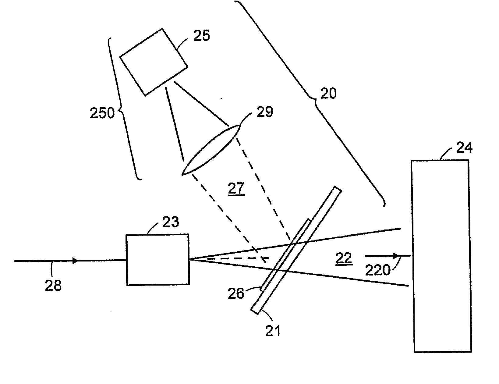
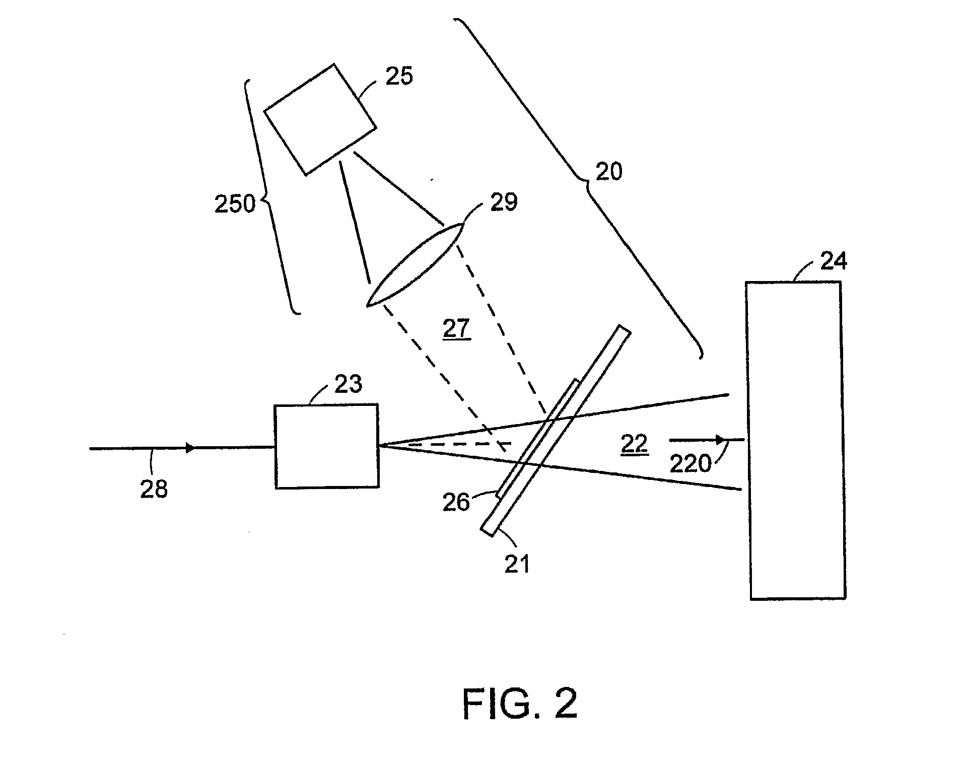
[0019] Referring to FIG. 2, a beam monitoring apparatus is designated generally by numeral 20. A thin screen 21 is placed in a beam 22 of charged particle between a nozzle 23 (that steers charged particles 28 generated by an accelerator, not shown) and an object 24 of irradiation, typically tissue of a human subject. It is to be understood that charged pa...


PUM


Abstract

A method and apparatus for monitoring a scanning beam of penetrating radiation, such as a scanning proton beam used to irradiate tissue. The position of the beam is tracked in real time by interposing a scintillator film between a source and an object of irradiation. An imaging detector, in optical communication with the scintillator, provides an output that is indicative of the position of the radiation and its variation with time. The accumulated dose over a scan may also be monitored.

Description

FIELD OF THE INVENTION [0001] The present invention pertains to a device and a method for monitoring, in real time, the spatial characteristics of a beam of penetrating radiation, and, more particularly, to a screen incorporating scintillator material that is disposed within the beam and that is optically imaged while a target object is irradiated. BACKGROUND ART Proton Therapy [0002] An objective of radiation therapy is to maximize and conform absorbed dose to a specified target volume that has been determined to contain diseased tissue, while, at the same time, minimizing dose to surrounding healthy tissue. The conformation of dose typically requires the use of multiple beams and control, dynamic or static, of the available geometric and dosimetric beam parameters. A unique advantage of charged particle beams, including protons or heavier ions, is the ability to control the penetration depth of the radiation dose, i.e., the Bragg peak location. This results in significant dosimet...

Claims


Application Information

Patent Timeline
IPC IPC(8): G01T1/20G01T1/24
CPCA61N5/1048A61N2005/1087G01T1/02G01T1/29G01T1/20G01T1/2914G01T1/023G01T1/201
Inventor EBSTEIN, STEVEN M.
Owner LEXITEK
Learn More