Measurement system to measure a physiological condition in a body

a physiological condition and measurement system technology, applied in the field of measurement systems, can solve the problems of inability to meet the requirements of patient monitors, inability to meet the requirements of blood pressure transducers and monitors, and the resulting standards that have evolved, and achieve the effect of small and light, more user-friendly

Inactive Publication Date: 2011-05-24
ST JUDE MEDICAL COORDINATION CENT
View PDF15 Cites 165 Cited by
  • Summary
  • Abstract
  • Description
  • Claims
  • Application Information

AI Technical Summary

Benefits of technology

[0021]In particular the present invention obviates the need of a physical galvanic connection between the patient and the monitoring device by arranging a physical optical link connection between an easy-to-use transceiver unit and a communication unit, and in particular that the measured pressure data is received by the transceiver unit where it preferably is processed and then transferred to the communication unit as a output signal. The transceiver unit, when receiving sensor data from the sensor, is adapted to self-contained, directly or at a later time, generate an optical transmission of data to the communication unit. The transceiver unit is provided with an energy means adapted to energize the sensor, the transceiver unit and also the optical communication link, thereby obviating any energy transfer from the communication unit to the transceiver unit. Thus, the optical communication link ensures that the transceiver unit is completely galvanically isolated from the communication unit.
[0024]Furthermore, a major advantage of the present invention is that no user input is required in order to use the system, instead it is ready to plug-in and directly use and that the sensor signal adapting circuitry then automatically adapts the output to the applied sensor signal.

Problems solved by technology

However, the blood pressure transducers and monitors that have been previously used, and the resulting standards that have evolved, are not without drawbacks.
As such, the accuracy of such systems has suffered due to variations in hydrostatic pressure and other inconsistencies associated with the fluid column.
Unfortunately, the electrical configurations of these miniaturized semiconductor sensors are not always compatible with the transducer amplifiers in existing patient monitors.
For instance, the miniaturized sensors often cannot operate over the entire range of excitation signal magnitudes and frequencies found among the various types of patient monitors.
Thus, they cannot be connected directly to many of the patient monitors already in use.
Such an arrangement necessitates additional circuitry on the interface and, because existing monitors have been designed to provide only limited amounts of power, the additional circuitry may require an independent source of electrical power.
As a consequence, use of the newer miniaturized sensors often adds cost and complexity to the overall system.
As discussed, this does not conform to the electrical format required by the many monitors that are commercially available and already in widespread use.
As such, the newer sensors can only be used with specific monitor types, thereby requiring additional, and often redundant, equipment to be purchased.
This is especially undesirable given the cost sensitivities so prevalent in today's health care environment.
An obvious drawback of the device of U.S. Pat. No. 5,568,815 is that, in order to connect the sensor to the monitor, a separate additional unit in the form of the interface circuit is required.
An additional risk occurs in patents which are undergoing defibrillation while having an electrically conductive transducer attached.

Method used


Image

  • Measurement system to measure a physiological condition in a body
  • Measurement system to measure a physiological condition in a body
  • Measurement system to measure a physiological condition in a body

Examples


first embodiment

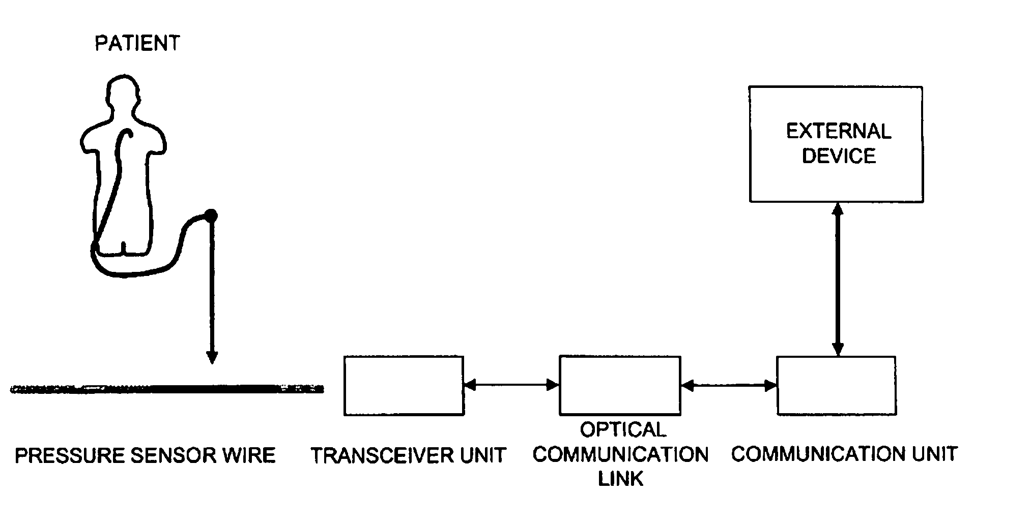
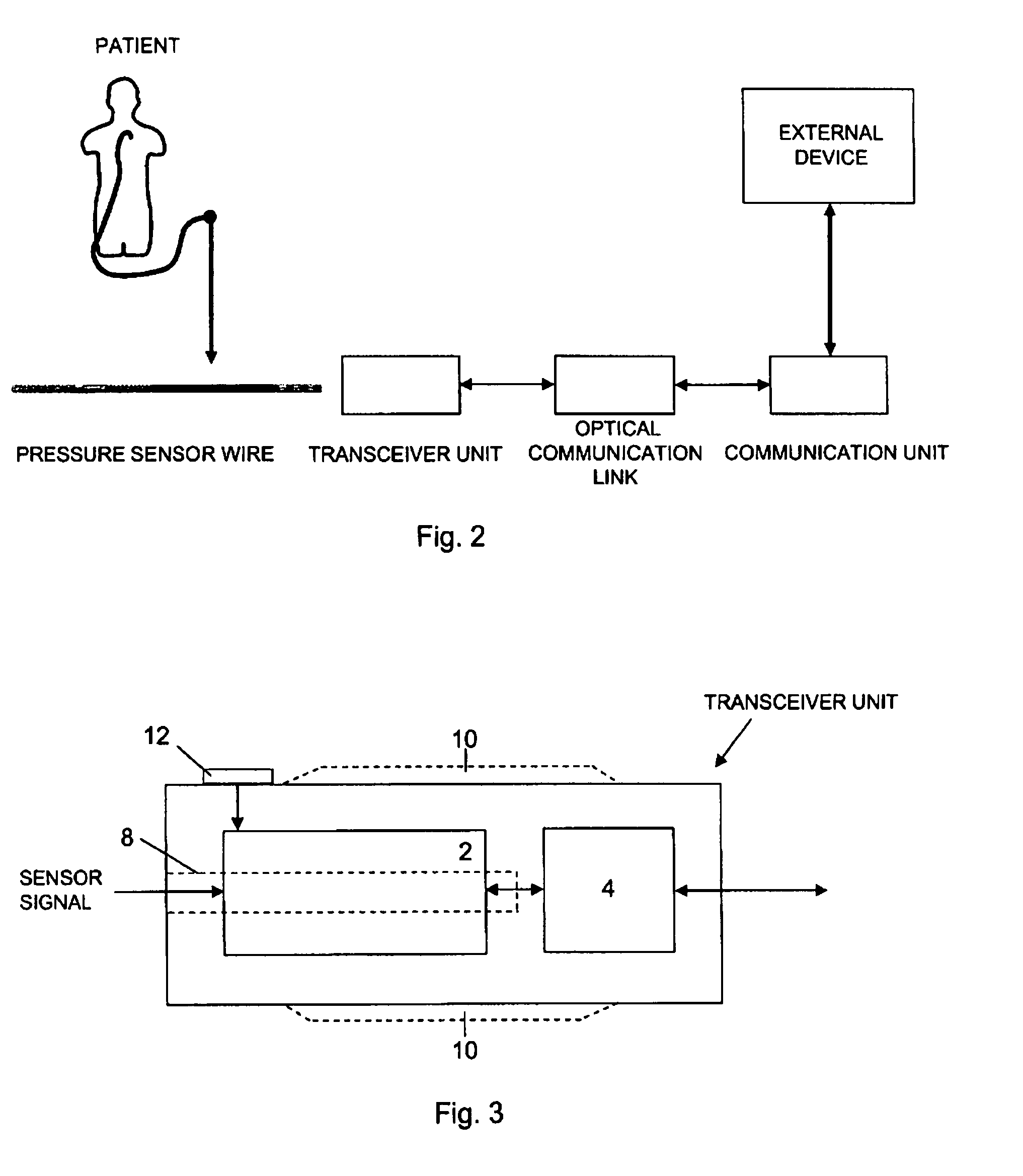
[0067] the communication is a one-way communication from the transceiver unit (and the sensor) to the communication unit (and external device). In this embodiment the light emitting diode is arranged at the side facing the transceiver unit and the photo detector faces the communication unit.

second embodiment

[0068]According to the invention the communication is a both-way communication, and in that case two optocouplers are arranged enabling communication in both directions.

[0069]For both embodiment more than one optocoupler may be arranged in either direction to provide redundancy for the optical communication link.

[0070]When the sensor wire has been inserted into the transceiver unit and the communication unit is connected to the external device the system is ready for use.

[0071]By e.g. pressing the activation button on, or by activating the transceiver in another way, the transceiver unit it is activated and will then try to establish an optical connection with the communication unit via the optical connector link. This is preferably performed by a conventional handshake procedure in order to identify the transceiver unit. The system is now ready to receive measured sensor data.

[0072]The sensor values is preferably A / D converted and supplied to the optical communication link as a pul...


PUM


Abstract

Measurement system comprising a sensor wire provided, at its distal end, with a physiological condition sensor to measure a physiological condition inside a patient, and to provide measured data to an external device, the measurement system comprises a transceiver unit adapted to be connected to the proximal end of the sensor wire, and a communication unit arranged in connection with the external device. The transceiver unit is adapted to communicate, by a communication signal, with the communication unit, in order to transfer measured data to the external device. The communication signal, including the measured data, is generated by the transceiver unit and transferred as an output signal and the communication unit is arranged to be connected to a standard input / output connector of the external device and to communicate with the external device in accordance with an established standard, or in accordance with relevant parts of an established standard, e.g. BP22 or USB. The measurement system further comprises a physical optical communication link arranged between the transceiver unit and the communication unit, wherein the communication signal is an optical signal transferred by the optical communication link. The transceiver unit also comprises an energy means adapted to energize the sensor, the transceiver unit and also the optical communication link.

Description

FIELD OF THE INVENTION[0001]The present invention relates to a measurement system comprising a transceiver unit and a communication unit for measuring a physiological condition in a body of a patient, according to the preamble of the independent claim.BACKGROUND OF THE INVENTION[0002]In many medical procedures, medical personnel need to monitor various physiological conditions that are present within a body cavity of a patient. These physiological conditions are typically physical in nature—such as pressure, temperature, rate-of-fluid flow—and provide the physician or medical technician with critical information as to the status of a patient's condition. Obviously, the manner by which these types of parameters are measured and monitored must be safe, accurate and reliable.[0003]One device that is widely used to monitor such conditions is the blood pressure transducer. A blood pressure transducer senses the magnitude of a patient's blood pressure, and converts it into a representativ...

Claims


Application Information

Patent Timeline
Patent Type & Authority Patents(United States)
IPC IPC(8): A61B5/00A61B5/02A61M25/00
CPCA61B5/0215A61B5/6851A61B5/0017A61M25/09A61B2560/0271A61B2560/045A61B2562/225A61B2560/0223
Inventor HUBINETTE, ULRIK
Owner ST JUDE MEDICAL COORDINATION CENT
Why Eureka
Try Eureka