Optical asset tracking system

a technology of asset tracking and optical equipment, applied in the field of asset tracking, can solve the problems of emi generated by rf communications of an rtls, affecting the operation of rtls, and hindering the tracking capability of rtls,

Inactive Publication Date: 2005-06-02
CELEVATORON LABS
View PDF18 Cites 151 Cited by
  • Summary
  • Abstract
  • Description
  • Claims
  • Application Information

AI Technical Summary

Benefits of technology

[0010] In another aspect the invention features an optical tag for generating an optical data signal including asset data. The optical tag includes an optical modulator, a memory module for storing asset data, and a tag processor in electrical communication with the optical modulator and the memory module. The tag processor generates a data signal in response to the asset data and the optical modulator generates an optical data signal in response to the data signal. In one embodiment the optical tag also includes an environmental sensor in electrical communication with the tag processor. In another embodiment the optical tag also includes a control circuit in electrical communication with the tag processor and the optical modulator. The control circuit provides a control signal in response to the data signal. In a further embodiment the optical tag also includes a trigger sensor to detect an interrogation signal. The trigger sensor is in communication with the tag processor and the control signal is responsive to the detection of the interrogation signal at the trigger sensor.

Problems solved by technology

Electromagnetic interference (EMI) generated by equipment such as welders, electric motors and other machinery can hinder tracking capability.
Conversely, EMI generated by RF communications of an RTLS can interfere with sensitive equipment such as computer controlled machinery and health care equipment.
In addition, because RTLSs typically operate in unlicensed frequency bands, various wireless communications that increasingly clutter these frequency bands can interfere with RTLS operations.
Furthermore, RTLS communications generate RF signals which can penetrate unshielded buildings and enclosures.
Thus security is at risk because valuable information such as inventory levels can be ascertained by outside observers monitoring the RF signals.

Method used


Image

  • Optical asset tracking system
  • Optical asset tracking system
  • Optical asset tracking system

Examples


Embodiment Construction

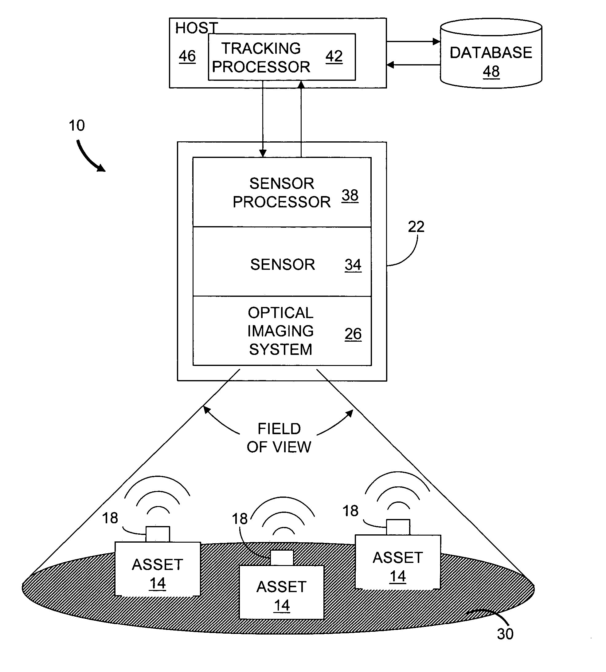
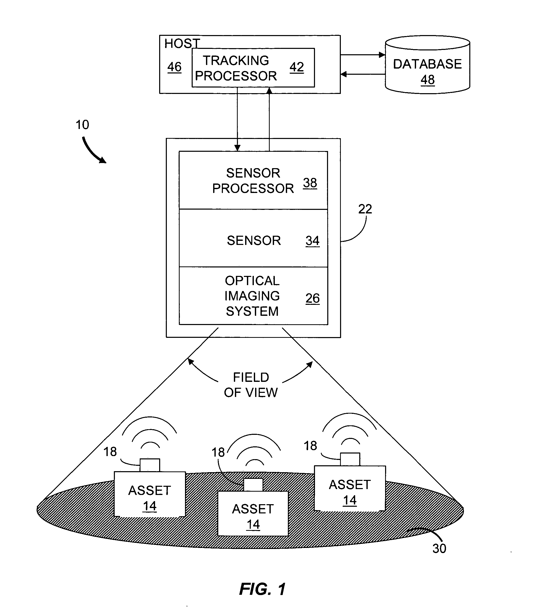
[0019]FIG. 1 is a block diagram illustrating an embodiment of an optical asset tracking system 10 according to the present invention. Affixed to each asset 14 is an optical tag 18 that includes an optical modulator, such as an optical source (e.g., light emitting diode (LED) or laser) or a modulated reflector. The optical modulator transmits asset data by way of an optical signal to an optical communications imager 22. The optical communications imager 22 includes an optical imaging system 26 to generate an image of a monitored area 30, or tracking region, on a sensor 34 having an array of pixels. Each pixel includes circuitry to receive high-speed optical communications data and to contribute data for generation of a video signal. The optical communications imager 22 also includes a sensor processor 38 for extracting the data in one or more optical signals incident on the array of pixels. Thus the optical asset tracking system can track a significant number of assets 14 within its ...


PUM


Abstract

Described are a system and a method for optical tracking of assets. The system includes a sensor having a plurality of pixels. Each pixel is adapted to produce an electrical signal responsive to an incident optical data signal emitted by an optical tag attached to an asset. The system also includes a sensor processor in communication with the sensor and configured to generate an electrical data signal based on optical data signals incident on the pixels. The sensor processor also generates asset data in response to the electrical data signals from the pixels. The sensor and sensor processor can be implemented as an optical communications imager in which each pixel generates a communication data signal based on incident light. Alternatively, the sensor can include a digital video camera or an analog video camera for lower bandwidth communications.

Description

FIELD OF THE INVENTION [0001] The invention relates generally to asset tracking. More particularly, the invention relates to a system and method for tracking assets based on an optical communications imager and optical tags attached to each asset to be tracked. BACKGROUND [0002] The location and status of assets can be determined using different means of asset tracking. For example, equipment, inventory and personnel can be tracked so that their position and status can be determined at different times. One common type of asset tracking is based on barcodes attached to the assets. The barcodes are examined with a barcode reader or scanner. Another type of asset tracking is based on passive radio frequency identification (RFID) tags attached to the assets. The RFID tags are read using a radio frequency (RF) interrogation device. According to either type of asset tracking, assets are tracked as they pass by checkpoints equipped with the appropriate readers. Checkpoints are frequently i...

Claims


Application Information

Patent Timeline
Patent Type & Authority Applications(United States)
IPC IPC(8): G06K7/10G06K17/00
CPCG06K7/10079G06K2017/0045G06K19/0728G06K7/1097
Inventor WILSEY, PHILIP A.BEYETTE, FRED R. JR.DIECKMAN, DARRYL S.MARTIN, DALE E.
Owner CELEVATORON LABS
Why Eureka
Try Eureka