An implementation method and circuit for low voltage output loop of plasma TV power supply

A low-voltage output, plasma technology, applied to color TV parts, TV system parts, TVs, etc., can solve the problems of insufficient pins, increased cost, high cost, etc., to achieve insufficient pins, realize high efficiency, Easy to adjust the effect

Inactive Publication Date: 2010-11-03
吴壬华
View PDF5 Cites 3 Cited by
  • Summary
  • Abstract
  • Description
  • Claims
  • Application Information

AI Technical Summary

Problems solved by technology

[0005] One method is to make a special transformer skeleton, which solves the problem of insufficient pins due to the large number of output channels, see figure 2 (Take 4 outputs as an example); however, due to the large number of output channels of the transformer, it will inevitably bring about the problem that the secondary turn ratio of the transformer is not easy to determine, and the transformer skeleton needs to be molded separately, which will increase the cost.
[0006] Another method is that the main transformer only has 2 to 3 circuits, and the other uses a buck circuit. Since the main transformer only has symmetrical windings (such as 12V and 24V), this solves the problem that the turn ratio of the secondary side of the transformer is not easy to determine. See image 3 (Taking 4-way output as an example); but because the other lines need to be output by buck circuits, the cost is relatively high, and the efficiency is relatively low (<94%)

Method used


Image

  • An implementation method and circuit for low voltage output loop of plasma TV power supply
  • An implementation method and circuit for low voltage output loop of plasma TV power supply
  • An implementation method and circuit for low voltage output loop of plasma TV power supply

Examples


Embodiment Construction

[0028] In order to facilitate a further understanding of the present invention, the present invention will now be described in detail with reference to the accompanying drawings and embodiments.

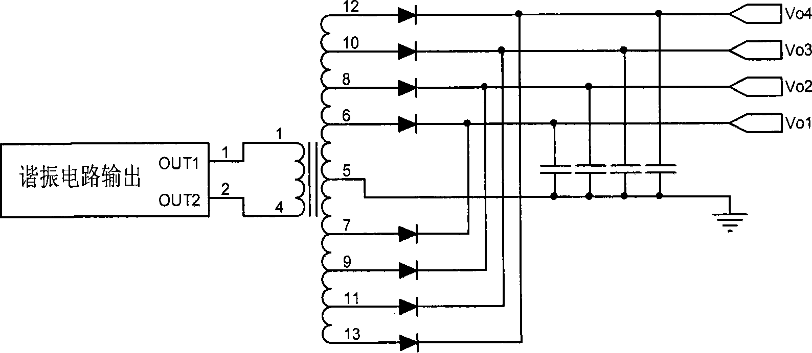
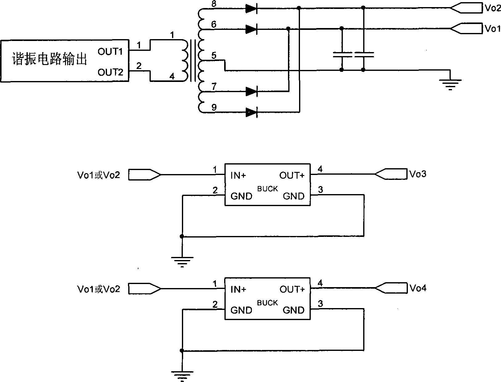
[0029] see Figure 4 As shown, including the main transformer (T1), the first rectifier diode (D1), the second rectifier diode (D2), the third rectifier diode (D3), the fourth rectifier diode (D4), the fifth rectifier diode (D5) and The sixth rectifier diode (D6), at least one autotransformer (T2); the first filter capacitor (C1), the second filter capacitor (C2), the third filter capacitor (C3); the second autotransformer (T2), The seventh rectifier diode (D7), the eighth rectifier diode (D8), the fourth filter capacitor (C4);

[0030] The primary side of the main transformer (T1) is connected to the output of the resonant circuit, the C terminal of the secondary side is connected to the anode of the first rectifying diode (D1), the D terminal is connected to the anode of the secon...


PUM


Abstract

The invention discloses an implementation method of low-voltage output loop for plasma TV power supply and the circuit thereof. The circuit thereof includes a main transformer (T1), a first commutation diode (D1), a second commutation diode (D2), a third commutation diode (D3), a fourth commutation diode (D4), a fifth commutation diode (D5), a sixth commutation diode (D6), and at least one autotransformer (T2); wherein the primary side of the main transformer (T1) is connected with the output of a resonance circuit, the C end of the secondary side is connected with the anode of the first commutation diode (D1), the D end is connected with the anode of the second commutation diode (D2), the F end is connected with the anode of the third commutation diode (D3), the G end is connected with the anode of the fourth commutation diode (D4), and the E end is earthed. The invention solves the problem of insufficient transformer base pins due to too many output lines, and furthermore the transformer secondary side has the advantages of convenience for adjusting the turn ratio, low cost and high implementation efficiency.

Description

technical field [0001] The invention relates to the technical field of power electronics, in particular to a method and circuit for realizing a low-voltage output circuit of a PDP (plasma television) power supply. Background technique [0002] PDP (Plasma TV) power supply is the heart of the whole TV, responsible for providing power supply for all screens and signal boards. like figure 1 As shown, its output is generally divided into four parts, standby output part (generally 5V), Vs circuit part (generally 175 ~ 210V), Va circuit part (generally 55 ~ 85V), LV (low voltage output) circuit part . Among them, the LV circuit is the most complicated, and the LV circuit is also different according to the different requirements of the screen and signal board. Generally composed of 33V, 24V, 15V, 12V, 9V, 5V, 3.3V. The least consists of three outputs (12V, 24V, 5V), and the most consists of 7 outputs. The general PDP power supply is composed of 4 or 5 channels. [0003] At pr...

Claims


Application Information

Patent Timeline
Patent Type & Authority Patents(China)
IPC IPC(8): H04N5/63
Inventor 吴壬华李英
Owner 吴壬华
Why Eureka
Try Eureka