Suction cup structure
A technology of suction cups and discs, which is applied in the direction of suction cups, connecting components, mechanical equipment, etc.
- Summary
- Abstract
- Description
- Claims
- Application Information
AI Technical Summary
Problems solved by technology
Method used
Image
Examples
Embodiment Construction
[0016] In order to make the above-mentioned purposes, features, and advantages of the present invention more obvious and easy to understand, a preferred embodiment of the sucker structure according to the present invention will be cited below, and it will be described in detail as follows in conjunction with the accompanying drawings, wherein the same elements Description will be made with the same reference numerals.
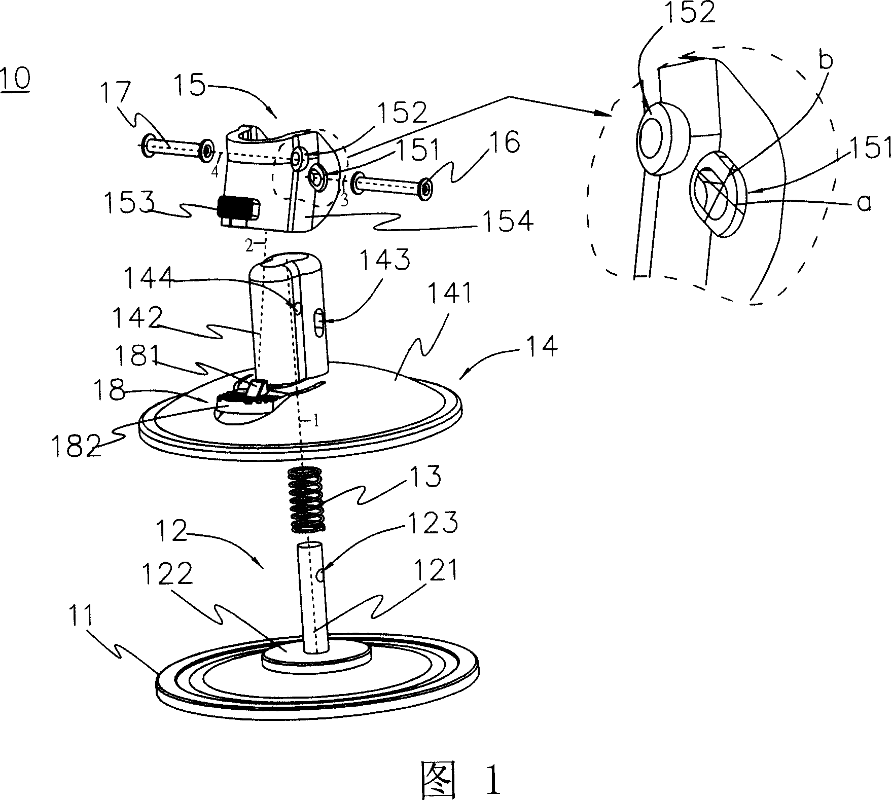
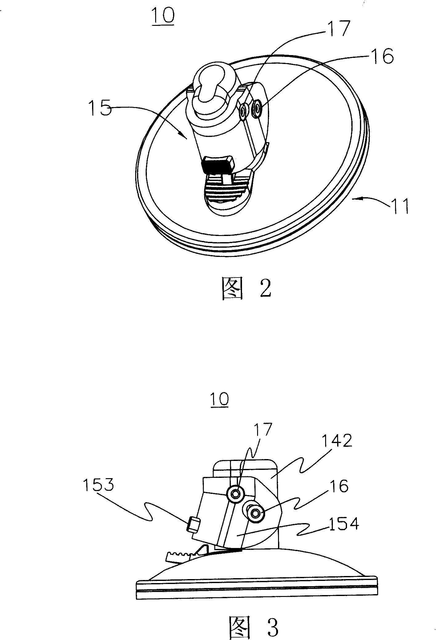
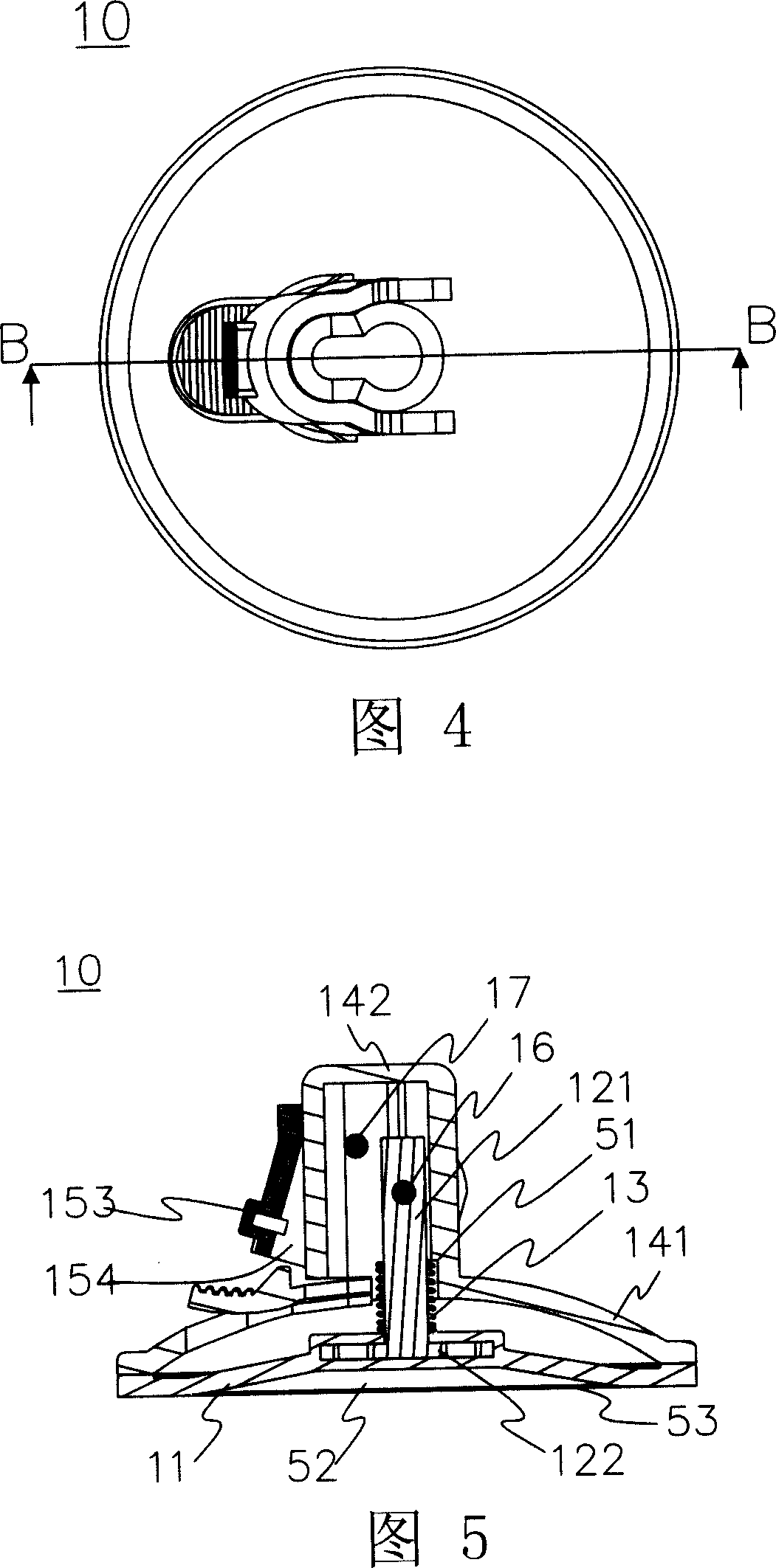
[0017] Please refer to FIG. 1 , which is a three-dimensional exploded view of the suction cup structure of the present invention. In the figure, this suction cup structure 10 comprises suction cup 11, pull rod 12, spring 13, bracket seat 14, button arm 15, slide pin 16 and shaft pin 17, wherein, suction cup 11 is plate-shaped and slightly flexible, and pull rod 12 has A rod body 121 and a circular plate 122, one end of the rod body 121 is vertically connected to the center of the circular plate 122, and the circular plate 122 is embedded in the suction cup 11 (...
PUM
 Abstract
Description
Claims
Application Information
 - R&D
- Intellectual Property
- Life Sciences
- Materials
- Tech Scout
- Unparalleled Data Quality
- Higher Quality Content
- 60% Fewer Hallucinations
Browse by: Latest US Patents, China's latest patents, Technical Efficacy Thesaurus, Application Domain, Technology Topic, Popular Technical Reports.
© 2025 PatSnap. All rights reserved.Legal|Privacy policy|Modern Slavery Act Transparency Statement|Sitemap|About US| Contact US: help@patsnap.com


