Synchronous monitoring control method of digital camera

A digital video camera, monitoring and control technology, applied in TV, color TV, image communication, etc., can solve the problem of centralized monitoring of the second monitoring area, and achieve the effect of effective monitoring and shooting of the event occurrence area

Inactive Publication Date: 2008-01-30
LEJIN GUANGDIAN ELECTRONIC CO LTD SHANGHAI
View PDF0 Cites 7 Cited by
  • Summary
  • Abstract
  • Description
  • Claims
  • Application Information

AI Technical Summary

Problems solved by technology

[0007] However, in a general digital video camera, as mentioned above, depending on whether an event occurs or not, only a simple action of selecting and recording a surveillance video can be performed, so for example, as shown in FIG. In the first area, the second camera takes pictures of the second area where the event occurs at the wide angle set by default, so there is a problem that the second monitoring area cannot be monitored intensively

Method used


Image

  • Synchronous monitoring control method of digital camera
  • Synchronous monitoring control method of digital camera
  • Synchronous monitoring control method of digital camera

Examples


Embodiment Construction

[0023] Embodiments of the digital video camera synchronous monitoring method of the present invention will be described in detail below with reference to the accompanying drawings.

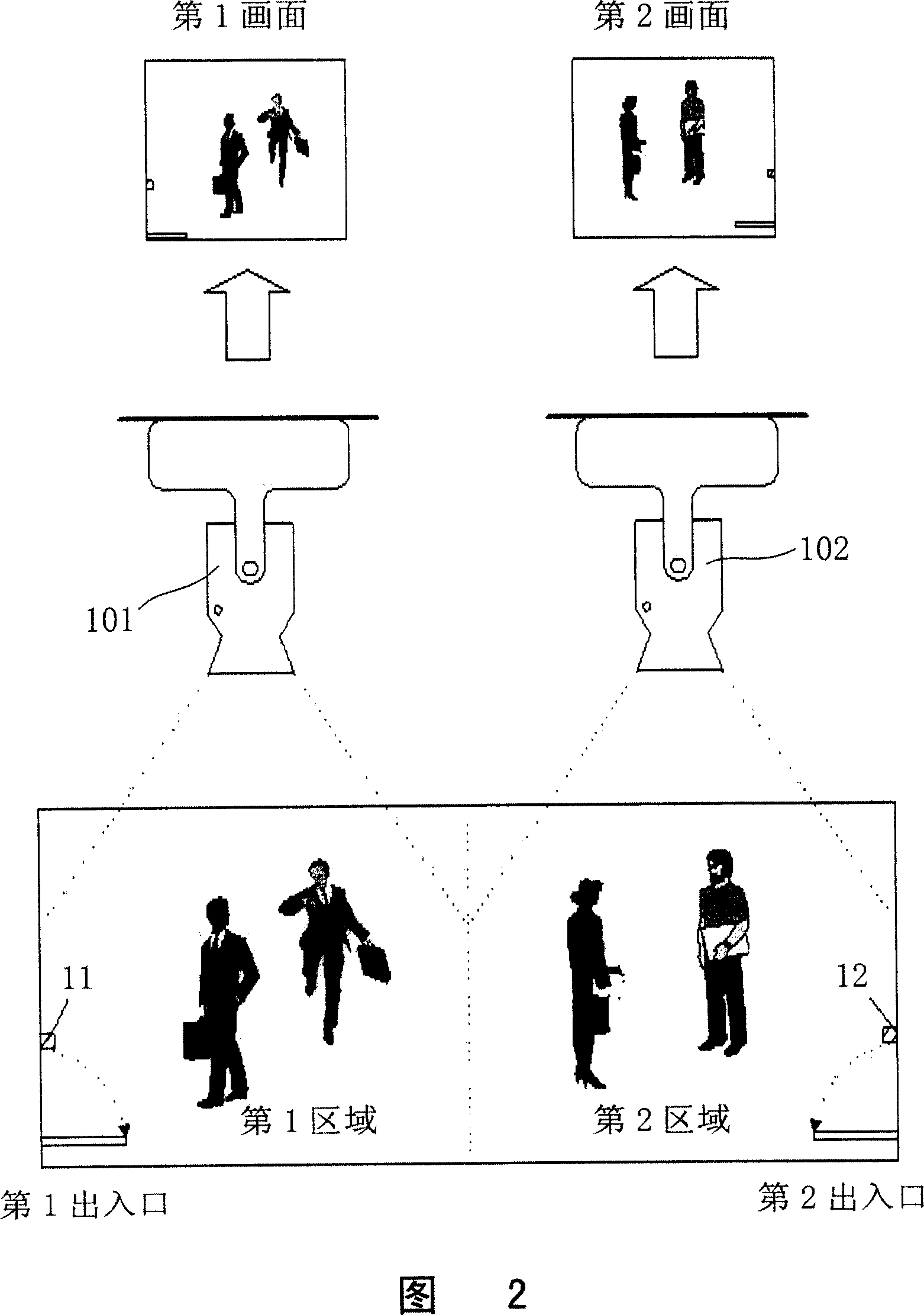
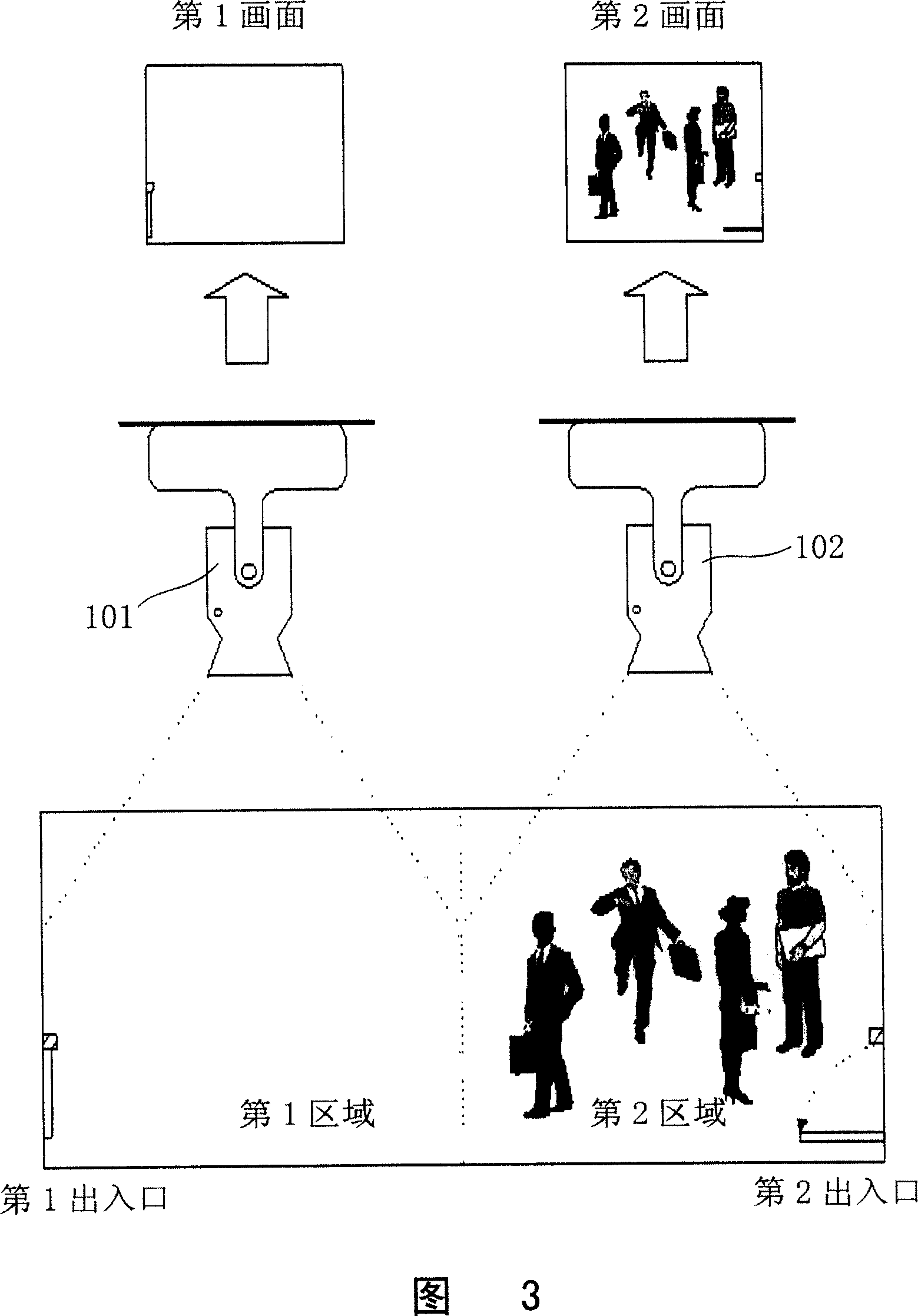
[0024] FIG. 4 is a schematic workflow diagram of a digital video camera synchronous monitoring control method according to the technology of the present invention, for example, refer to FIG. 2 .

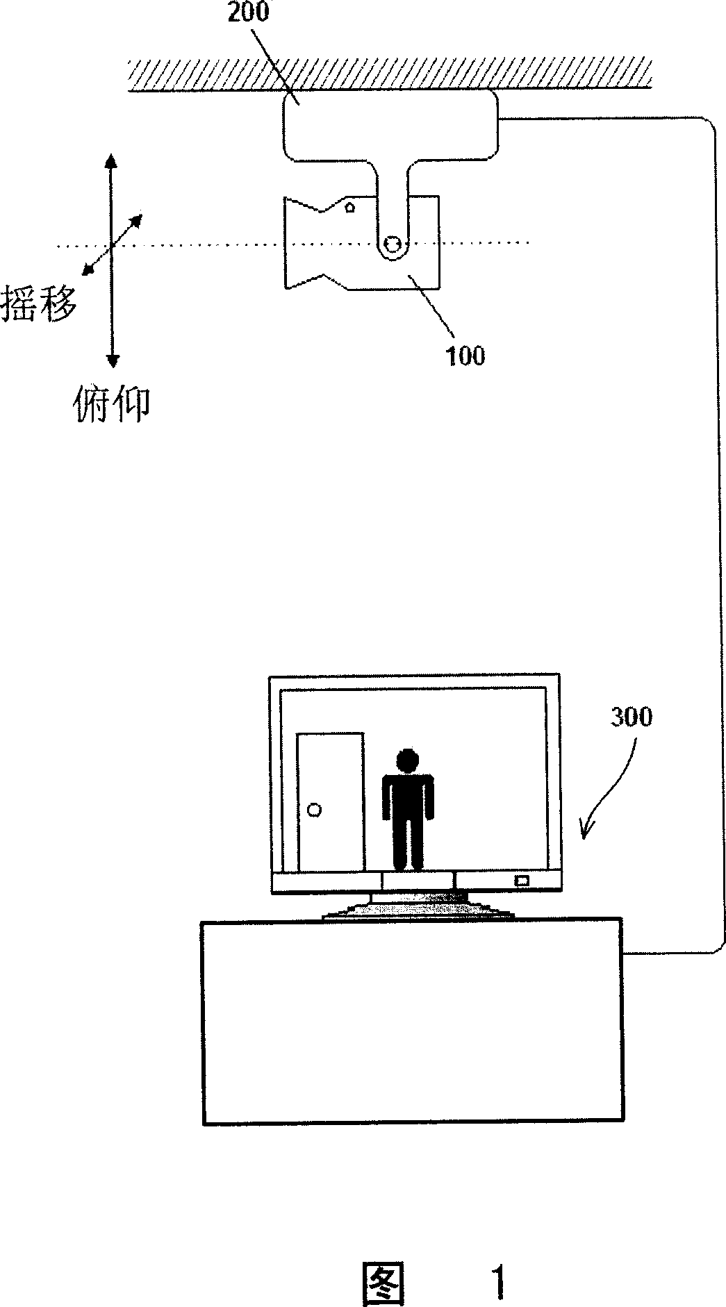
[0025] Steps 10 and 11, as mentioned above, set the first camera (Cam1) 101 and the first sensor (Sensor1) 11 on the ceiling of the first monitoring area (Area1) and the first entrance (Door1), and set the first sensor (Sensor1) 11 in the second monitoring area ( The ceiling of Area2) and the second entrance (Door2) are provided with a second camera (Cam2) 102 and a second sensor (Sensor2) 12. At the same time, when the above camera and sensor are connected to a digital video camera (DVR), if according to the user's requirements When it is set to the synchronous monitoring mode (Cooperation Monitoring Mo...


PUM


Abstract

The invention relates to a synchronous monitoring and controlling method of a digital video camera which consists of a plurality of monitoring cameras provided with the functions of pan, tilt and zooming and sensors. If a synchronous monitoring mode is set, event occurrence can be judged in a plurality of monitoring areas that are mutually different with each other. If the judging result is that the monitoring areas with event and the monitoring areas with no event exist simultaneously, the pan, tilt and zooming control is carried out for a plurality of monitoring cameras that are screening all the monitoring areas and at the same time the monitoring areas with event occurrence is monitored. In addition, when in the process, if a new event occurs in the monitoring areas without event, the pan, tilt and zooming control is carried out for a plurality of monitoring cameras and all the monitoring areas are restored into an initial setting state for screening. The invention can more effectively monitor and screen the monitoring areas with event by adding and utilizing the monitoring cameras in the monitoring areas without event.

Description

technical field [0001] The present invention relates to the synchronous monitoring control method of digital video camera, especially refer to in the digital video camera (DVR) that is connected together with a plurality of monitoring cameras and sensors with pitch / sway / zooming (PTZ) function, if set as synchronous monitoring Mode, a digital video camera synchronous monitoring control method that uses surveillance cameras in areas where events do not occur to more effectively monitor areas where events occur. Background technique [0002] Generally speaking, a surveillance PTZ camera with tilt / pan / zoom functions is mounted on a pitch / tilt platform (Pan&Tilter) fixedly installed on the ceiling of a specific place. For example, as shown in Figure 1, the above-mentioned PTZ surveillance camera 100 passes The above-mentioned pitch / sway platform 200 performs a panning action of a horizontal 360-degree rotation and a vertical 180-degree rotation of a tilting (Tilting) action, ther...

Claims


Application Information

Patent Timeline
Patent Type & Authority Applications(China)
IPC IPC(8): H04N7/18H04N5/232
Inventor 金建旭
Owner LEJIN GUANGDIAN ELECTRONIC CO LTD SHANGHAI
Why Eureka
Try Eureka