Spray gun

A spray gun and paint spraying technology, applied in the direction of spraying devices, spraying devices, liquid spraying devices, etc., can solve the problems of dirty hands, reluctance to change the spraying method, etc., and achieve the effect of low complexity

Inactive Publication Date: 2008-02-20
J WAGNER GMBH
View PDF0 Cites 18 Cited by
  • Summary
  • Abstract
  • Description
  • Claims
  • Application Information

AI Technical Summary

Problems solved by technology

Therefore, in many cases, operators are reluctant to change spray patterns in order to avoid paint getting their hands dirty

Method used


Image

  • Spray gun
  • Spray gun
  • Spray gun

Examples


Embodiment Construction

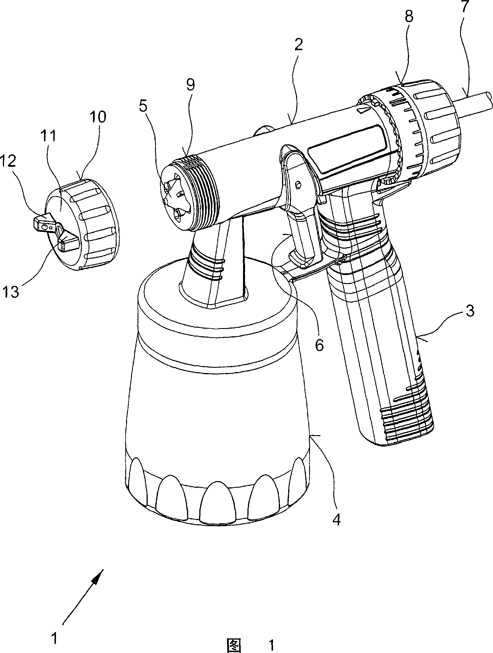
[0024] The spray gun shown in Fig. 1 numeral 1 is used for spraying paint or paint, mainly comprises the gun casing 2 that accommodates propulsion mechanism, realizes the parts of mixing and / or metering, the handle 3 that protrudes from gun casing 2, and is used for preserving Storage container 4 for the processed medium. The medium extracted from the storage container 4 is atomized by compressed air supplied through the gun housing 2 via the line 7 of the atomizing nozzle 5 . In the example shown, the atomizing nozzle 5 is held by a union nut 10 screwed onto a thread 9 machined on the gun housing 2 . The nozzle needle 16 to the atomizing nozzle 5 is controlled by the handle 6 and the amount of paint is controlled by the adjusting screw 8 .

[0025] The spray gun 1 has an air cap 11, shown in Figures 12a, 12b and 12c, by which the air cap 11 can be rotated to produce three different jets I, II and III, namely a horizontally oriented flat jet I, a round jet II and Vertically ...


PUM


Abstract

In a spray gun ( 1 ) for spraying paint with a gun housing ( 2 ) provided with a handle ( 3 ) with a union nut ( 10 ) screwed onto it that holds an air cap ( 11 ) provided with offset outlet openings ( 14, 15 ) for compressed air, the union nut ( 10 ) is positively connected to the air cap ( 11 ) in a circumferential direction. This embodiment makes it possible for the spray jet to be set in a brief time and without difficulties without having to put up with getting dirty. It is merely necessary to turn the union nut ( 10 ) accordingly in order to control the air supply to the outlet openings( 14, 15 ) of the air cap ( 11 ) and therefore to influence the formation of the spray jet.

Description

technical field [0001] The present invention relates to a spray gun for spraying paint and similar viscous media relying on compressed gas or electric propulsion, which comprises a gun housing containing said propulsion mechanism, spray gun components for mixing and / or metering, a secondary gun housing a handle protruding from the body, a removable storage container attached to the gun casing for storing media, and a joint nut placed on the gun casing or an intermediate piece connected to the gun casing or extension tube, and a surrounding Air cap for a coupling nut with mutually offset outlets for compressed air, in this way different sprays can be formed, as well as an atomizing nozzle which is held in a directional position and can be opened by means of a nozzle needle . Background technique [0002] Spray guns of this type have been marketed many years ago by J. Wagner Gmbh, Markdorf under the name W850E, and they have proven their effectiveness in practice. In this ex...

Claims


Application Information

Patent Timeline
Patent Type & Authority Applications(China)
IPC IPC(8): B05B9/01B05B1/12B05B12/00B05B15/00
CPCB05B7/083B05B7/0815B05B7/2435
Inventor A·戈林G·齐默曼E·克拉耶
Owner J WAGNER GMBH
Why Eureka
Try Eureka