
Method and circuit for dual PWM mixed cut wave control switch part

A control circuit and control switch technology, applied in the field of control, can solve the problems of poor turn-on continuous regulation performance, large turn-on regulation dead zone, etc.

Inactive Publication Date: 2008-03-26
NORTH CHINA ELECTRIC POWER UNIV (BAODING)
View PDF0 Cites 7 Cited by
  • Summary
  • Abstract
  • Description
  • Claims
  • Application Information

AI Technical Summary

Problems solved by technology

At present, the series pole speed regulation of asynchronous motor generally adopts the method of high-frequency chopping control of IGBT. Since the opening and closing process of IGBT takes a certain time, in the process of chopping control, in order to ensure that the IGBT can be turned off reliably and turn-on, the time that the IGBT is in the off state each time should not be less than a minimum duration, which accounts for about 10% of the period of the PWM signal period of the high-frequency chopping control, resulting in a PWM chopping control IGBT of about 10% turn-off dead zone, the adjustment range of high-frequency chopping control is only about 0-90%
Therefore, the existing PWM high-frequency chopper control device has the disadvantages of a large dead zone in turn-on adjustment and poor performance in continuous turn-on regulation.

Method used


Image

  • Method and circuit for dual PWM mixed cut wave control switch part
  • Method and circuit for dual PWM mixed cut wave control switch part

Examples


Embodiment Construction

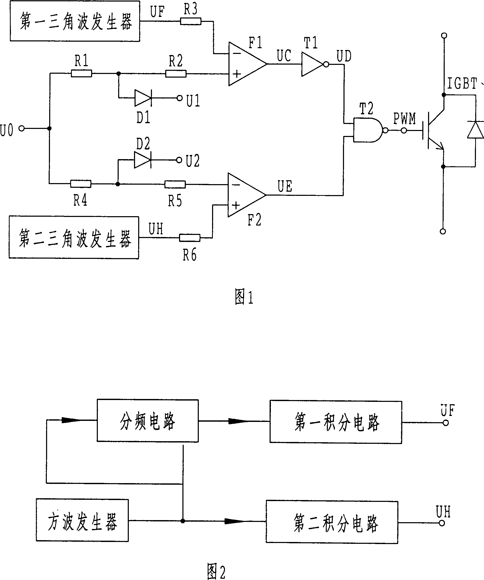
[0016] Referring to Fig. 1, the present invention adopts two main and auxiliary PWM chopper circuits to control the IGBT at the same time. In the auxiliary PWM chopper circuit, the given adjustment input U0 is sequentially connected to the positive direction of the operational amplifier F1 through the resistance R1 and the resistance R2. At the input terminal, the anode of the limiting diode D1 is connected to the series connection point of the resistor R1 and the resistor R2, and the cathode is connected to the limiting voltage U1, and the output terminal of the first triangular wave generator is connected to the reverse input terminal of the operational amplifier F1 after passing through a coupling resistor R3. The output terminal of the operational amplifier F1 is connected to an input terminal of the NAND gate T2 after passing through the NOT gate T1; in the main PWM chopper circuit, the given adjustment input value U0 is connected to the reverse input of the operational amp...


PUM


Abstract

This invention relates to a method and a circuit for controlling switch devices by dual PWM mixed chopping, which utilizes a chopper control circuit to control on / off of a switch device IGBT, in which, the circuit includes two, and signals output by which control the same IGBT by an NAND gate, and the period of the output signals of the sub-PWM chopper control circuit is integer multiple of that of the master PWM and the least turned-off time of the sub-PWM is equal to a period of the output pulse control signal output by the master one, and pulse signals output by the master and sub-PWM operate on NOT AND logic operation to control on / off of the IGBT.

Description

technical field [0001] The invention relates to a method for controlling an IGBT by using a PWM chopper control circuit, which belongs to the technical field of control. Background technique [0002] The high-frequency chopper control circuit is widely used in the series pole speed control device of the asynchronous motor because of its low cost and excellent performance, especially in the large and medium-sized fans and water pumps in the electric power, mining, petroleum, building materials and other industries. Among the speed regulation and energy saving control devices, it is even more popular. At present, the series pole speed regulation of asynchronous motors generally adopts the method of high-frequency chopping control of IGBT. Since the opening and closing process of IGBT takes a certain time, in the process of chopping control, in order to ensure that the IGBT can be turned off reliably and turn-on, the time that the IGBT is in the off state each time should not ...

Claims


Application Information

Patent Timeline
IPC IPC(8): H02M1/08H02P25/00
Inventor 董清颜湘武
Owner NORTH CHINA ELECTRIC POWER UNIV (BAODING)
Learn More