
Electricity generating device

A technology of power generation device and control rope, applied in wind power generation, wind turbine components, engines, etc., to achieve the effect of simple facilities

Inactive Publication Date: 2012-07-18
刀祢明 保信
View PDF2 Cites 0 Cited by
  • Summary
  • Abstract
  • Description
  • Claims
  • Application Information

AI Technical Summary

Problems solved by technology

[0007] However, the wind power generation device described in Patent Document 2 requires a special system or mechanism in order to properly adjust the relationship between the two floating bodies and operate it.

Method used


Image

  • Electricity generating device
  • Electricity generating device
  • Electricity generating device

Examples


Embodiment Construction

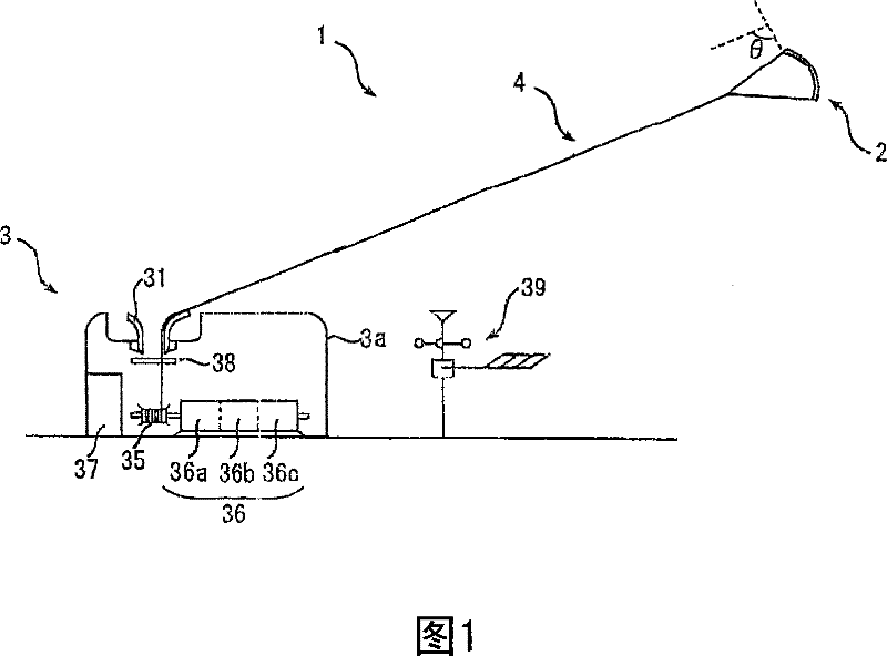
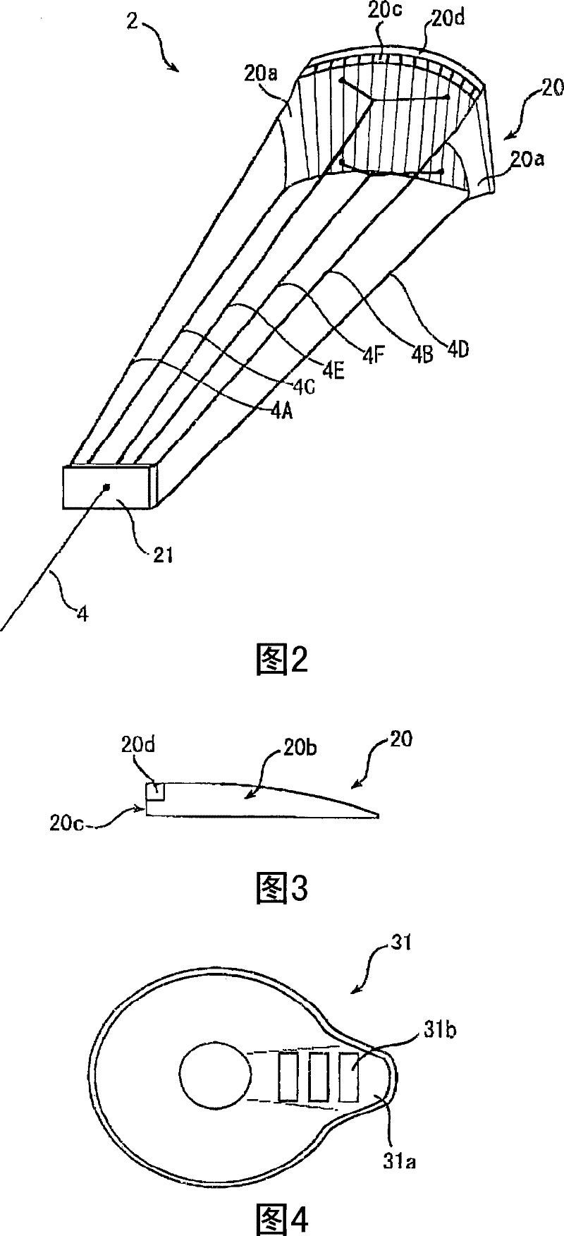
[0048] The best mode for carrying out the present invention will be described below with reference to the accompanying drawings. figure 1 It is a schematic view showing the overall structure of the power generating device 1 according to the first embodiment of the present invention. Such as figure 1As shown, the power generating device 1 has a floating body 2 , a base body 3 , and a control rope 4 . The main body of the floating body 2 swims (moves freely) under the flow of air above, that is, under the force of the wind; And the function of generating electricity; the base end of the control rope 4 is connected with the base body 3 , and the front end is connected with the swimming body 2 . Furthermore, examples of the swimming body 2 include a so-called kite, a glider, a balloon, and the like. In addition, the base body 3 is a part that operates for power generation on land, ocean, lake, or river, and it is only necessary to control its relative position with the swimming...


PUM


Abstract

The present invention provides a power generation device in which a motion body (kites etc.) and a generator are separated, and the power is gotten by simple devices. The power generation device includes a motion body bearing wind, a substrate supporting and controlling motion body, a controlling rope that controls and connects the motion body with the substrate, the substrate includes a controlling rope incoming and outgoing pipe which the controlling rope passes through, a coiler winding the controlling rope, a generator which generates power by rotation of coiler's axis, a motor which has the coiler rotated, the motion body can control the first dip and the second dip, which repeat with electric period during power generation alternatively, wherein, the power generation period is that the motion body of the first dip leave from the substrate and has the axis of the coiler rotated in the first direction to generate power; the electric period is that the axis of the coiler rotates inthe second direction by the motor to have the motion body of the second dip been close to the substrate.

Description

technical field [0001] The present invention relates to a power generating device using a floating body that swims under the flow of air. Background technique [0002] As wind power generators that generate power by receiving air flow, power generators that generate electric power by rotating a shaft (rotor) of a generator coupled with blades that rotate by wind force are widely used. Generally, this wind power generation device has a high height in order to withstand the wind far from the ground, and the facility is very large in order to support the huge blades. [0003] Various proposals have been made to suppress the enlargement of such facilities. For example, in the wind power generator described in Patent Document 1, the blades and the generator are downsized by making the rotor and the stator rotate in opposite directions relative to each other. [0004] In addition, in the wind power generator described in Patent Document 2, two floating devices (swimming bodies) ...

Claims


Application Information

Patent Timeline
Patent Type & Authority Patents(China)
IPC IPC(8): F03D5/06F03D11/00F03D7/00F03D9/00
CPCY02E10/723Y02E10/725Y02E10/722Y02E10/70Y02E10/72
Inventor 刀祢明保信
Owner 刀祢明 保信
Learn More