Electrode mixture paste coating method and coater

A coating method and mixture technology, which are applied in electrode collector coating, electrode manufacturing, alkaline battery electrodes, etc., can solve the problems of reduced coating dimensional accuracy and inability to improve.

Inactive Publication Date: 2008-04-23
PANASONIC CORP
View PDF2 Cites 4 Cited by
  • Summary
  • Abstract
  • Description
  • Claims
  • Application Information

AI Technical Summary

Problems solved by technology

If the core material is to be wound on a roll dipped in such a high-viscosity electrode mixture slurry, and the roll is rotated to coat the electrode mixture slurry on the core material, there is a problem that the surface of the roll is smooth. Next, the high-viscosity electrode mixture slurry infiltrated between the roller and the core material will not escape from the holes formed on the core material due to its high viscosity, so the core material floats from the outer peripheral surface of the roller, and the core material The material meanders, so that the coating dimensional accuracy of the core material in the width direction is reduced
But it doesn't improve the problem

Method used


Image

  • Electrode mixture paste coating method and coater
  • Electrode mixture paste coating method and coater

Examples


Embodiment 1

[0028] In water with a wet ball mill, the composition formula MmNi 3.55 co 0.75 mn 0.4 Al 0.3 The shown hydrogen storage alloy was pulverized to an average particle diameter of 30 µm to obtain a hydrogen storage alloy powder. After immersing the hydrogen storage alloy powder in an alkaline aqueous solution for surface treatment, 10 kg of a carboxymethyl cellulose aqueous solution having a solid content ratio of 1.5% and 0.4 kg of Ketjen black were added to 100 kg of the hydrogen storage alloy powder. After kneading, 1.75 kg of an aqueous solution of styrene-butadiene copolymer rubber particles having a solid content ratio of 40% was added and stirred to prepare electrode mixture slurry 6 .

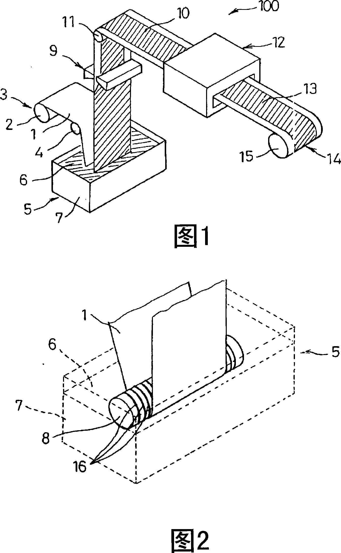
[0029] The core material 1 (the total length of the core material coil 2 is 200 m) is composed of a nickel-plated iron punching metal with a thickness of 60 μm, a width of 300 mm, a punching diameter of 1 mm, and an opening ratio of 42%. On both sides, the electrode mixture slurry 6 was ...

Embodiment 2~5

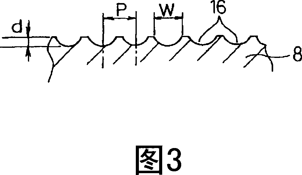
[0032] For Example 1, the pitch interval P of the grooves 16 formed on the surface of the roller 8 is set to 50mm (Example 2), 25mm (Example 3), 7mm (Example 4), and 5mm (Example 5), The electrode mixture slurry 6 was coated on the core material 1 in the same manner as in Example 1 except that the groove width w was set to the groove pitch interval P×0.8.

[0033] On the core material 1, the electrode mixture slurry 6 is coated in a range of 200m, and then at the rearmost part of the electrode slurry coating sheet 10 (the position where the coating is completed), measure the distance from one end of the core material 1 to the electrode mixture. The size of the application part of the slurry 6. As a result, with respect to the initial setting value of 20 mm, the offset amounts were 1.6 mm (Example 2), 0.7 mm (Example 3), 0.3 mm (Example 4), and 1.0 mm (Example 5).


PUM


Abstract

A coating method by which a stripe core material (1) made of a punched thin metal plate is fed in the longitudinal direction, the core material (1) is wound around a part of the outer circumference of a roll (8) immersed into electrode mixture paste (6), the opposite sides of the core material (1) are coated with the electrode mixture paste (6) by traveling the core material (1) through rotation of the roll (8), coating thickness of the electrode mixture paste (6) is adjusted and then the electrode mixture paste (6) thus applied is dried, a groove (16) is formed in the outer circumferential surface of a roll (8) along the rotational direction, the electrode mixture paste (6) entering between the outer circumference of the roll (8) and the core material (1) is discharged smoothly in order to suppress snaking of the core material (1) and deterioration in precision of coating dimension is avoided, thus realizing a coating method of electrode mixture paste by which deterioration in precision of coating dimension can be avoided even in the case of high viscosity electrode mixture paste.

Description

technical field [0001] The present invention relates to an electrode mixture slurry coating method and a coating device, and particularly relates to an electrode mixture slurry capable of coating both sides of a core material made of a perforated metal sheet with required precision and good production yield Coating method and coating device. Background technique [0002] Batteries such as alkaline storage batteries and lithium ion secondary batteries are widely used as power sources for portable devices, electric tools, or electric vehicles. Among them, nickel-metal hydride storage batteries with high energy density and excellent durability are mainly used as power supplies for electric vehicles, and their applications are expanding. [0003] Generally speaking, the main components of a nickel-metal hydride storage battery include: a positive electrode composed of nickel hydroxide filled in a three-dimensional metal porous body, and a core material composed of a perforated ...

Claims


Application Information

Patent Timeline
Patent Type & Authority Applications(China)
IPC IPC(8): H01M4/04H01M4/26
CPCY02E60/124H01M4/0404H01M4/26Y02E60/10
Inventor 臼井广幸南野圭史
Owner PANASONIC CORP
Why Eureka
Try Eureka