Automatic calibration composite video signal cable transmission equipment
A composite video signal and cable transmission technology, which is applied in the direction of cable transmission adaptation, can solve problems such as difficult adjustment of engineering requirements, and achieve the effect of convenient use and enhanced transmission distance
- Summary
- Abstract
- Description
- Claims
- Application Information
AI Technical Summary
Problems solved by technology
Method used
Image
Examples
Embodiment 1
[0029] is a specific example of transmission over twisted pair cables.
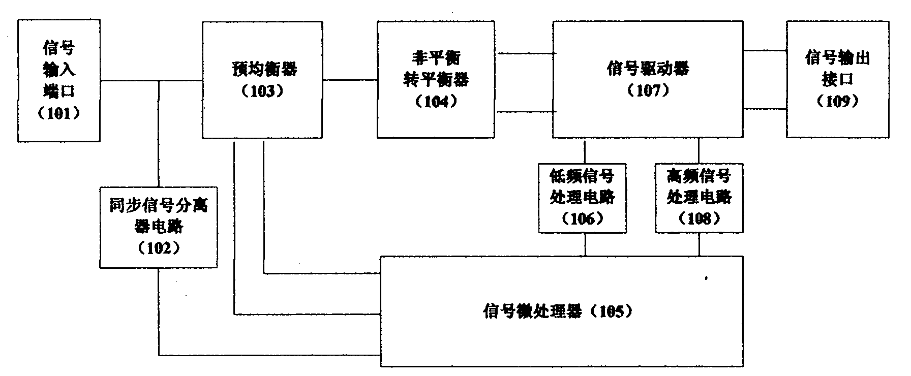
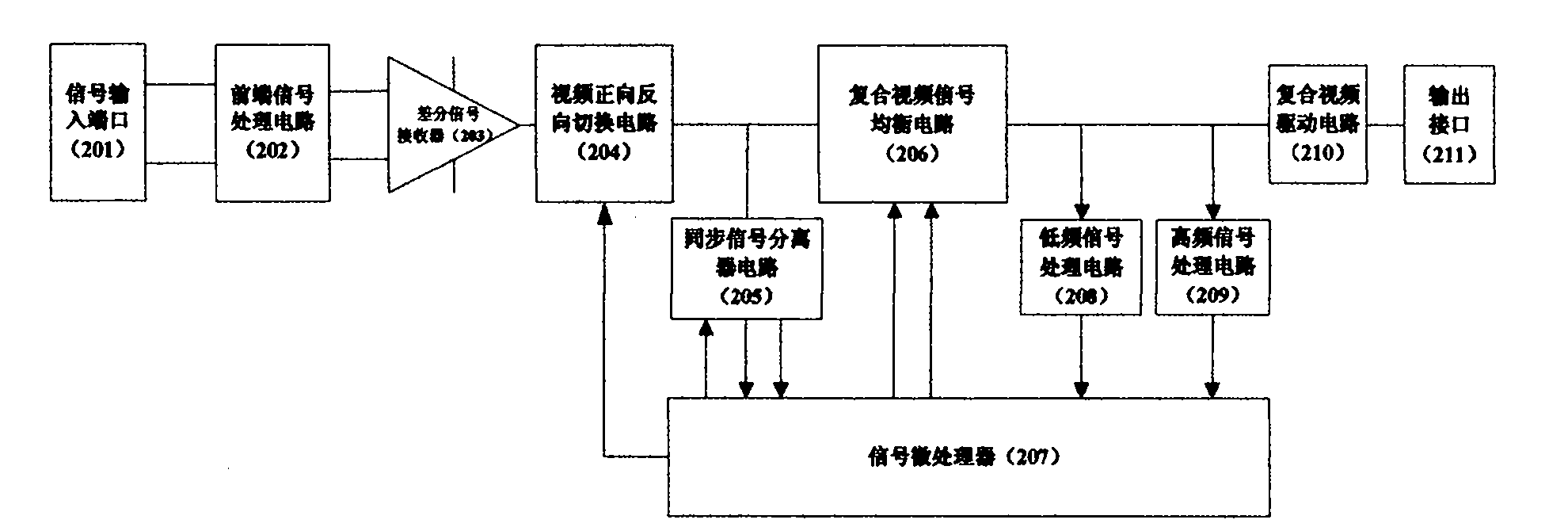
[0030] The transmitting device pre-gains the transmitted signal by analyzing the characteristics of the line. The receiving device automatically analyzes the type of video signal, and at the same time analyzes the attenuation of the signal, and the signal size reference of the standard signal, and obtains the best video signal quality by equalizing the signal.
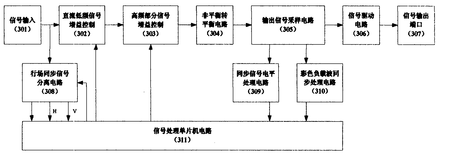
[0031] attached image 3 Shown is the system control block diagram of the signal transmitting part of the system equipment, which includes: a signal input (301) port, a DC low frequency signal gain control (302), a high frequency part signal gain control (303), and this part passes the signal micro The analysis of the online signal by the processor will automatically control the gain control of the low frequency signal and the high frequency signal. Unbalanced to balanced circuit (304), output signal sampling circuit (305), signal drive circuit ...
Embodiment 2
[0040] An embodiment of automatic equalization for long-distance transmission using coaxial cables. This example not only has long-distance signal automatic calibration function. It also has the functions of lightning protection, anti-jamming, and multi-channel output. The block diagram of the system structure diagram is attached Figure 9 shown. Including: signal input port (901), lightning protection circuit (902), anti-interference circuit (903), composite video signal equalization circuit (904), composite video distribution drive circuit (905), output port (906), synchronization signal separation A circuit (907), a low-frequency signal processing circuit (908), a high-frequency signal processing circuit (909), and a signal processing circuit (910).
[0041] When the system is not compatible with multiple composite video systems but only compatible with a single video signal, the synchronous signal separation circuit (907) can be canceled.
PUM
 Abstract
Description
Claims
Application Information
 - R&D
- Intellectual Property
- Life Sciences
- Materials
- Tech Scout
- Unparalleled Data Quality
- Higher Quality Content
- 60% Fewer Hallucinations
Browse by: Latest US Patents, China's latest patents, Technical Efficacy Thesaurus, Application Domain, Technology Topic, Popular Technical Reports.
© 2025 PatSnap. All rights reserved.Legal|Privacy policy|Modern Slavery Act Transparency Statement|Sitemap|About US| Contact US: help@patsnap.com


