A high-speed pulse signal pulse width precision control circuit and control method with self-calibration function

A high-speed pulse and precision control technology, which is applied in the field of high-speed pulse signal pulse width precision control and high-speed pulse signal pulse width precision control circuit, can solve the problems of large temperature drift, poor pulse width control accuracy, and non-monotonic delay. The circuit structure is simple, the difficulty of debugging is reduced, and the effect of high control precision

Active Publication Date: 2020-06-30
THE 41ST INST OF CHINA ELECTRONICS TECH GRP
View PDF6 Cites 0 Cited by
  • Summary
  • Abstract
  • Description
  • Claims
  • Application Information

AI Technical Summary

Problems solved by technology

[0005] (1) The operating frequency range of the circuit is small, and the upper limit of the operating frequency of the existing circuit is limited by the operating rate of the delay chip, and its operating frequency is generally below 1.5GHz
[0006] (2) The pulse width control accuracy is poor. In the existing pulse width control circuit, a multi-stage optional gate circuit is used as a pulse width control means. The delay is even non-monotonic, and there are few feasible ways to fine-tune the circuit other than manual point-by-point calibration
Moreover, the consistency of the circuit is poor, the debugging is difficult, the efficiency is low, and the productivity is poor
[0007] (3) The temperature drift is large, and the existing pulse width control circuit is greatly affected by the temperature change, and the delay temperature drift is generally more than 15% in the range of 0°C to 50°C, which requires an extremely complicated temperature compensation circuit to compensate, and After the compensation is calibrated, its accuracy generally can only stay at the level of hundreds of picoseconds

Method used


Image

  • A high-speed pulse signal pulse width precision control circuit and control method with self-calibration function
  • A high-speed pulse signal pulse width precision control circuit and control method with self-calibration function
  • A high-speed pulse signal pulse width precision control circuit and control method with self-calibration function

Examples


Embodiment Construction

[0043] The following will clearly and completely describe the technical solutions in the embodiments of the present invention with reference to the accompanying drawings in the embodiments of the present invention. Obviously, the described embodiments are only some, not all, embodiments of the present invention. Based on the embodiments of the present invention, all other embodiments obtained by persons of ordinary skill in the art without making creative efforts belong to the protection scope of the present invention.

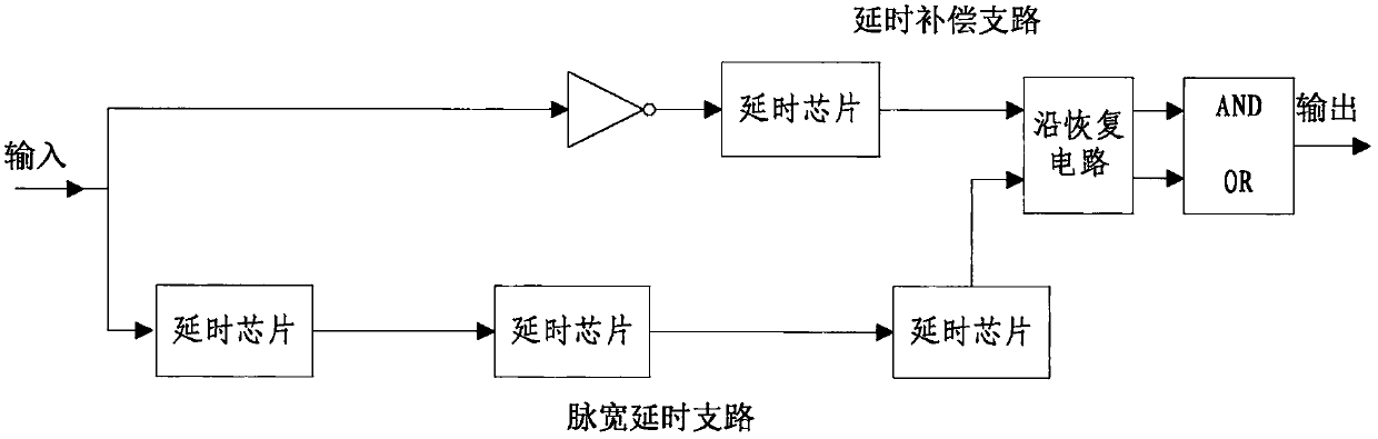
[0044] The traditional adjustable pulse width pulse signal generation circuit mostly uses delay circuit and logic gate circuit to realize the adjustment of pulse width. First, the pulse signal is divided into two channels, the first channel is normal output, the second channel passes through the programmable delayer, and the two signals pass through the AND gate or the OR gate to obtain the return-to-zero code pulse signal with a changed pulse width. The delay...


PUM


Abstract

The present invention proposes a high-speed pulse signal pulse width precision control circuit with a self-calibration function. The reference input clock passes through three PLLs to generate three coherent clock signals with the same frequency. The initial value of the frequency and phase accumulation word is used to adjust the phase of each PLL relative to the reference input clock, and then the three PLLs are synchronized by the synchronous trigger signal. The circuit structure of the present invention is simple, low in cost and low in power consumption, and is suitable for almost all high-speed pulse signal generators and Karpsu serial bit error meters; the minimum output pulse width is small, the control precision is high, and the minimum output pulse width can reach 100 ps. The pulse width control accuracy can reach 1ps; the working frequency is high, the highest working frequency can reach 4.1GHz; it has automatic calibration function, which can automatically compensate the error caused by the change of environment and temperature. The calibration circuit adopts pure digital design, and the calibration efficiency is extremely high. The difficulty of debugging has been greatly reduced.

Description

technical field [0001] The invention relates to the technical field of testing, in particular to a high-speed pulse signal pulse width precision control circuit with a self-calibration function, and also to a high-speed pulse signal pulse width precision control method with a self-calibration function. Background technique [0002] Pulse width adjustment is an important function of test instruments such as pulse signal generators and serial bit error detectors. The adjustment accuracy of existing pulse width adjustment circuits is mainly affected by factors such as the accuracy of the delay circuit and temperature. Because a wide range of controllable delay integrated circuits generally use cascaded logic gates to realize the stacking of delays, the discreteness of delays of logic gates becomes the most important factor affecting the accuracy of pulse width regulation circuits. [0003] The existing precise pulse width adjustment method is realized by using multi-level delay...

Claims


Application Information

Patent Timeline
Patent Type & Authority Patents(China)
IPC IPC(8): H03K7/08H03L7/07
CPCH03K7/08H03L7/07
Inventor 罗阳孟祥禄
Owner THE 41ST INST OF CHINA ELECTRONICS TECH GRP
Why Eureka
Try Eureka