
Conveyor system, especially airport baggage conveyor system

A conveying system and airport technology, applied in the field of conveying system, can solve advanced problems of data transmission

Inactive Publication Date: 2008-06-11
SIEMENS AG
View PDF6 Cites 10 Cited by
  • Summary
  • Abstract
  • Description
  • Claims
  • Application Information

AI Technical Summary

Problems solved by technology

Here, too, the host computer directly performs control in the form of target setting, which likewise has the disadvantage of high data transmission

Method used


Image

  • Conveyor system, especially airport baggage conveyor system
  • Conveyor system, especially airport baggage conveyor system

Examples


Embodiment Construction

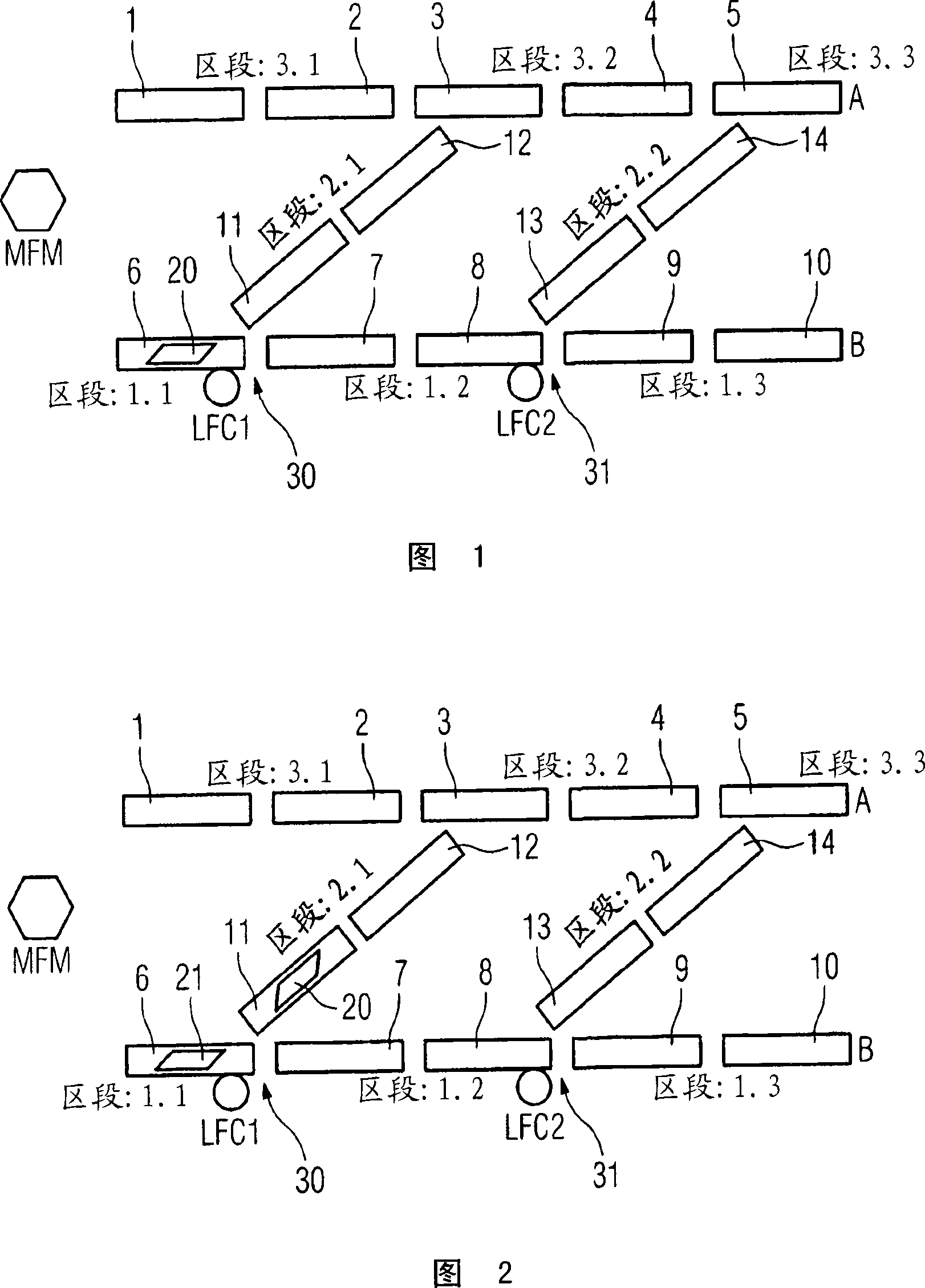
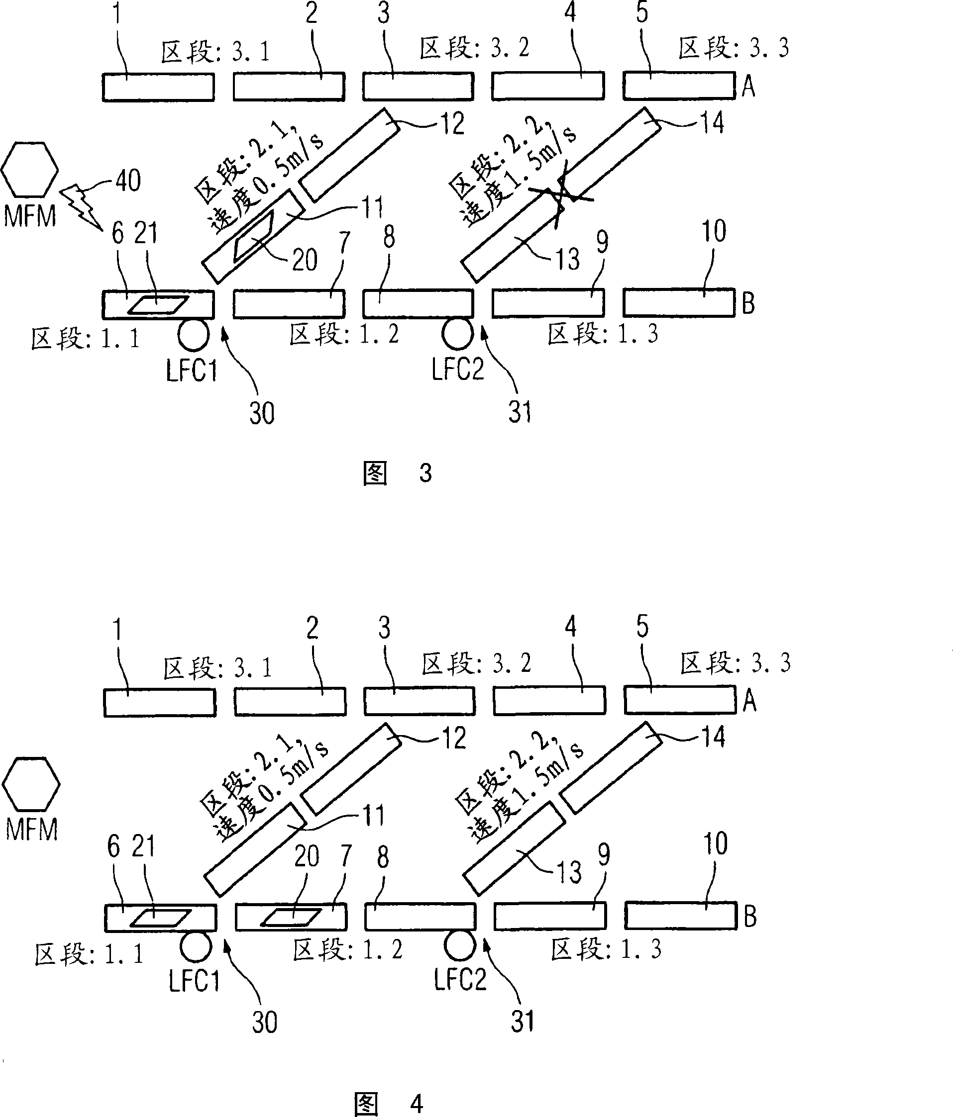
[0018] The conveying system shown in FIGS. 1-4 is formed from a large number of conveying subsections, which are referred to as sections 1.1-1.3, 2.1-2.2 or 3.1-3.3. Each section 1.1-3.3 is formed from one or two delivery sections 1-14, which can also be referred to as delivery modules. Two conveying branches formed by conveying sections 1-5 or 6-10 respectively lead from a feed point of the conveyed material not specified in detail to one of the two possible conveying destinations A and B respectively. . The conveying branch line formed by the conveying sections 6 - 10 has two branch points, which are designated by the reference numerals 30 , 31 . At these branching points 30, 31, the conveyed material, which in the present case lies on the conveying section 6 and is denoted by 20, can optionally be guided via the section 2.1 or the section 2.2 to another line with the conveying section 1- 5. Destination A of the delivery branch line. The branch points 30 , 31 are thus des...


PUM


Abstract

The invention relates to a conveyor system comprising an electronic control which provides a plurality of local material flow controls (LFC1, LFC2) and a material flow monitoring system (MFM). The local material flow controls (LFC1, LFC2) are associated with respective individual branch points (30, 31) in the conveyor system and calculate for every item conveyed (20, 21), upon its arrival in the area of the branch point (30, 31), the conveyor path towards the respective desired destination (A, B) while taking into consideration possible disturbances of individual conveyor sections (section 2.2). The local material flow controls (LFC1, LFC2) are provided with information on possible disturbances via a corresponding transmitting facility (40) of the material flow monitoring system (MFM) in the fashion of radio messages broadcast across the conveyor system.

Description

technical field [0001] The invention relates to a conveyor system according to the preamble of claim 1, in particular an airport baggage conveyor system. Background technique [0002] An airport baggage conveyor is known as a special conveyor system, for example, from DE 199 31 576 A1. In this case, the luggage items are conveyed along a conveyor line with a plurality of branch points to the respectively predetermined destinations. The transport control takes place here by means of a master control device, which brings the items of luggage along the conveyor line to the respective destination. The conveying route specification is carried out by means of a subordinate control device, which knows neither the destination nor the predetermined route. Thus, if the luggage reaches a branch point, the subordinate control unit will ask the main control unit, specifying the identification number of the luggage item, in which direction the luggage item should be conveyed further. T...

Claims


Application Information

Patent Timeline
IPC IPC(8): G06Q10/00
CPCG06Q10/08G06K17/0029G07G1/0045
Inventor J·斯蒂克
Owner SIEMENS AG
Learn More