Light valve module

A light valve and opto-mechanical technology, applied in the field of projectors, can solve the problems of poor contact, falling off, and inability to control the DMD chip correctly.

Inactive Publication Date: 2008-07-16
CORETRONIC
View PDF0 Cites 28 Cited by
  • Summary
  • Abstract
  • Description
  • Claims
  • Application Information

AI Technical Summary

Problems solved by technology

[0004] The bonding surface 12 of the DMD chip 12 is provided with a plurality of contacts (not shown) that are used to be electrically connected to the circuit board 14. These contacts must be able to all contact with the elastic pieces 131 of the seat 13 when assembling, so that the DMD The chip 12 is completely electrically connected to the circuit board 14. If one or more contacts of the DMD chip 12 are not in contact, it will be impossible to correctly control the operation of the DMD chip 12, resulting in bad situations such as white lines in the image.
And when the projector pursues exquisiteness and compactness, the internal components are all miniaturized as much as possible, and the space for the screw 18 to be locked is relatively limited, so the screw 18 with a smaller screw head will be used. Therefore, the b...

Method used


Image

  • Light valve module
  • Light valve module
  • Light valve module

Examples


Embodiment Construction

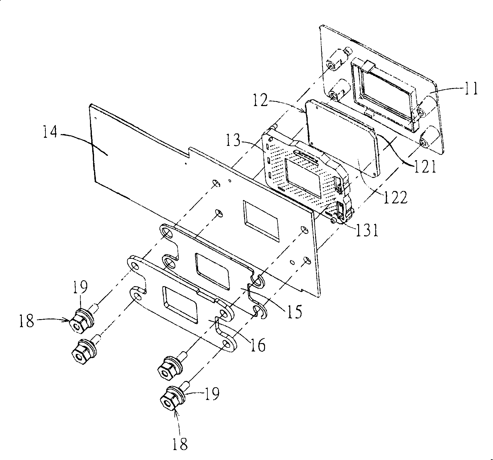
[0058] The foregoing and other technical contents, features and effects of the present invention will be clearly presented in the following detailed description of a preferred embodiment with reference to the drawings. Before the present invention is described in detail, it should be noted that in the following description, similar elements are denoted by the same reference numerals. In addition, here we first define a component whose side facing the optomechanical base is the front side, and the side facing away from the optomechanical base is the rear side.

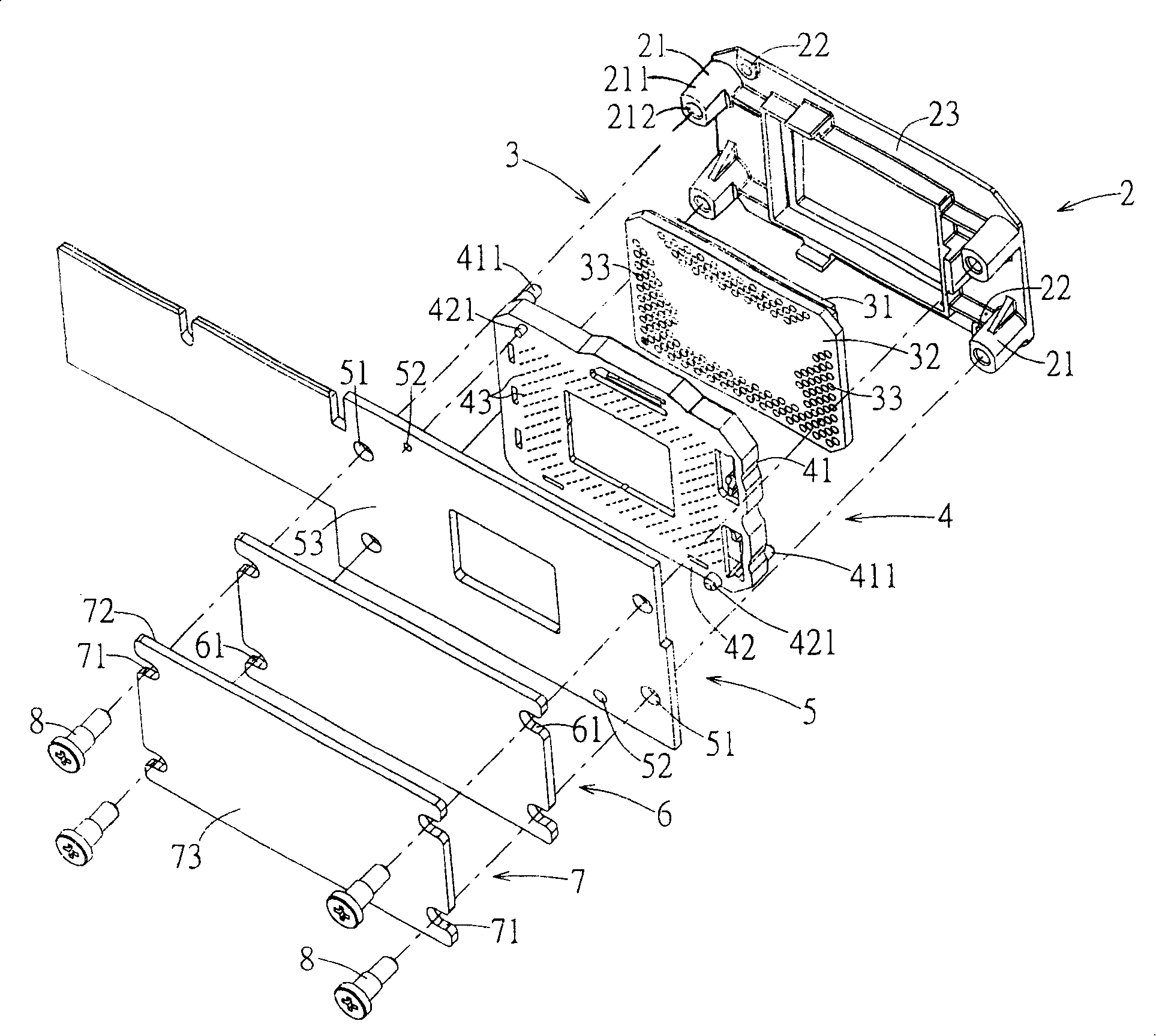
[0059] refer to image 3 As shown in FIG. 4 , the light valve module according to an embodiment of the present invention includes a display element, a seat 4 , a circuit board 5 , a buffer sheet 6 , and a rigid board 7 . The light valve module is suitable for being assembled on an optical machine base 2 by a plurality of screws 8, and the optical machine base 2 has a plurality of fixing parts 21. In this embodiment, fo...


PUM


Abstract

The invention discloses a light valve module which is suitable to be assembled on an optical machine base by screws. The light valve module comprises an imaging element, a carrier, a circuit board, a buffer piece and a rigid plate, wherein the whole piece of buffer sheet made of insulating material capable of elastic deformation is overlapped on the rear side of the circuit board; the rigid plate made of rigid material is overlapped on the rear side of the buffer sheet; the circuit board, the buffer sheet and the rigid plate are provided with a plurality of corresponding through holes or through grooves. The screws are orderly arranged through the corresponding through holes and the through grooves of the rigid plate, the buffer sheet and the circuit board to be locked in a fixing part of the optical machine base. With the improved buffer sheet, deflection caused by locking is easy to control and the number of assembly parts and assembly tolerance can be reduced.

Description

technical field [0001] The invention relates to a projector, in particular to a light valve module in the projector. Background technique [0002] Currently, projectors using digital optical processing (DLP) technology use a digital micro-mirror device (Digital Micro-mirror Device, DMD) as a display element. like figure 1 , 2, the assembly method of the existing DMD chip 12 is to support the light-incident surface 121 of the DMD chip 12 on an optical machine base 11, and then flatten a surface of a seat 13 provided with a shrapnel 131. Paste on the bonding surface 122 of the DMD chip 12 , and then attach a circuit board 14 to the other surface of the seat 13 . Since the material of the circuit board 14 itself is easily deformed, the other side of the circuit board 14 must be provided with a metal plate 16 to prevent the deformation of the circuit board 14; An insulating layer 15 is arranged between them, and the insulating layer 15 is a Mylar sheet. Generally, the DMD ch...

Claims


Application Information

Patent Timeline
IPC IPC(8): G03B21/14G03B21/00H04N5/74H04N9/31
Inventor 刘家伦张代立
Owner CORETRONIC
Why Eureka
Try Eureka