Heat sink

A technology for heat dissipation devices and bases, which is applied to pump devices, parts of pumping devices for elastic fluids, cooling/ventilation/heating transformation, etc., and can solve complex circuit design, offset of corresponding pole pieces, high production cost, etc. question

Inactive Publication Date: 2009-09-09
DELTA ELECTRONICS INC
View PDF1 Cites 2 Cited by
  • Summary
  • Abstract
  • Description
  • Claims
  • Application Information

AI Technical Summary

Problems solved by technology

[0007] However, the above-mentioned two conventional methods are not only complicated in circuit design, but also relatively reduce the available space on the circuit board and require high manufacturing costs. Moreover, the Hall sensing element does not bend when assembling

Method used


Image

  • Heat sink
  • Heat sink
  • Heat sink

Examples


Embodiment Construction

[0046] This case can be understood more deeply through the following diagrams and detailed descriptions.

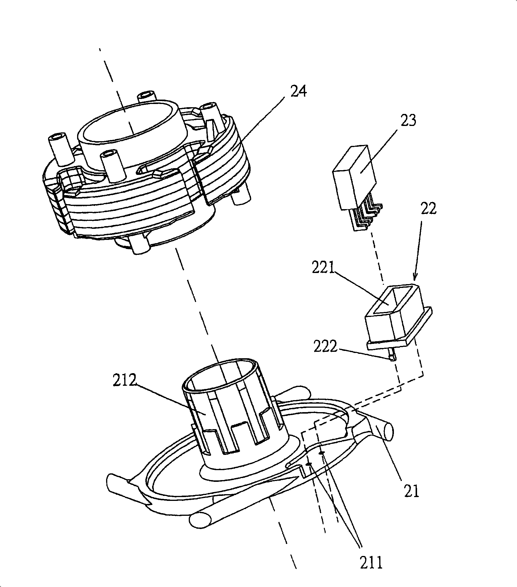
[0047] The invention discloses a motor control element and its fixing seat applied to a cooling fan, which uses a single drive control element to sense the phase change of the magnetic pole of the motor and control the operation of the fan motor. First, see figure 2 , which is the first preferred embodiment of the positioning method of the motor-driven control element of the present application. According to a conception of the present invention, the fixing seat 22 is substantially a square frame seat, which has a slot 221, which is formed according to the size and shape of the drive control element, for accommodating the drive control element to be inserted into There are hooks 222 on both sides of the bottom surface of the fixing seat, which can be fastened to the fastening holes 211 on the fan frame base 21 of the cooling fan, so that the fixing seat can be fixed on ...


PUM


Abstract

The invention provides a heat sink without a circuit board. The heat sink comprises a fan frame base; a motor which comprises a stator set sheathed on the base and a rotor set coupled on the base; a monoblock control element which is an integrated circuit, and directly drives and controls operation of the heat sink and induces magnetic pole phase change of the motor without a circuit board; and a fixing seat which is fixedly connected to the base and provided with a slot for accommodating the control element. The monoblock control element drives and controls operation of the heat sink and induce the magnetic pole phase change of the motor, thus the heat sink saves a traditional printed circuit board, which reduces number of parts, lowers manufacturing cost and time, and avoid complex circuit design.

Description

[0001] This application is a divisional application of Chinese Patent Application No. 03153909.2 with an application date of August 20, 2003 and an invention title of "Control Element Fixing Seat for Radiating Device". technical field [0002] The present invention relates to a fixing seat for a motor control element of a cooling device, in particular to a driving control element and its fixing seat of a brushless DC motor applied to a small heat dissipation fan and a heat dissipation device with the fixing seat. device. Background technique [0003] Currently, brushless DC motors have been widely used in various electronic products, such as cooling fans. Please see first Figure 1A , which shows an exploded view of the cooling fan, which includes a fan frame 11 , a printed circuit board 12 , a stator 13 and a rotor 14 . When assembling the fan, the printed circuit board 12 , the stator 13 and the rotor 14 are sequentially placed on the sleeve 111 of the fan frame base. ...

Claims


Application Information

Patent Timeline
IPC IPC(8): F04D29/64F04D29/06H05K7/20F04D25/06
Inventor 刘政杰周宜芳林祖亮蔡明熹林国正
Owner DELTA ELECTRONICS INC
Why Eureka
Try Eureka