Panel locking and regulating device for drawer with slide

An adjustment device and drawer technology, which is applied in the field of drawers with slide rails, can solve the problems of inability to adjust the left and right positions, poor safety, and pulling off the panel, so as to achieve the effect of improving safety, high degree of safety, and realizing left and right position adjustment

Active Publication Date: 2010-06-16
伍志勇
View PDF7 Cites 0 Cited by
  • Summary
  • Abstract
  • Description
  • Claims
  • Application Information

AI Technical Summary

Problems solved by technology

[0003] When the drawer rail assembly of this structure is used, the up and down installation position of the panel can be adjusted by adjusting the adjusting screw on the side. The one-way block connecting the shrapnel is separated from the slot of the soil rail, and then the entire drawer frame is separated from the upper rail, which provides certain convenience for installation, adjustment and use to a certain extent; however, the drawer guide rail assembly only The up and down position of the panel can be adjusted, but the left and right position cannot be adjusted. In normal use, the panel may be pulled off. The reason is that when the user opens the drawer, he pulls it obliquely upward instead of straight. , because the installation position of the drawers is generally relatively low, there are many cases where the drawers are pulled upwards and outwards obliquely, which is in line with the user's usage habits, and the manufacturer cannot emphasize that the drawers and panels shipped by the company are not allowed to be inclined upwards and outwards Pull, so its security is relatively poor

Method used


Image

  • Panel locking and regulating device for drawer with slide
  • Panel locking and regulating device for drawer with slide
  • Panel locking and regulating device for drawer with slide

Examples


Embodiment Construction

[0041] The present invention will be further described below in conjunction with the accompanying drawings and embodiments.

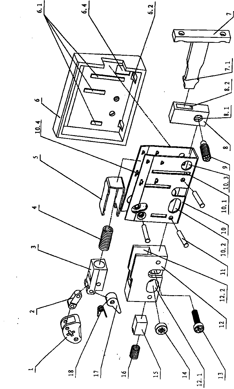
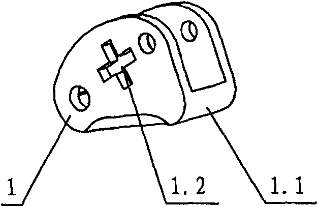
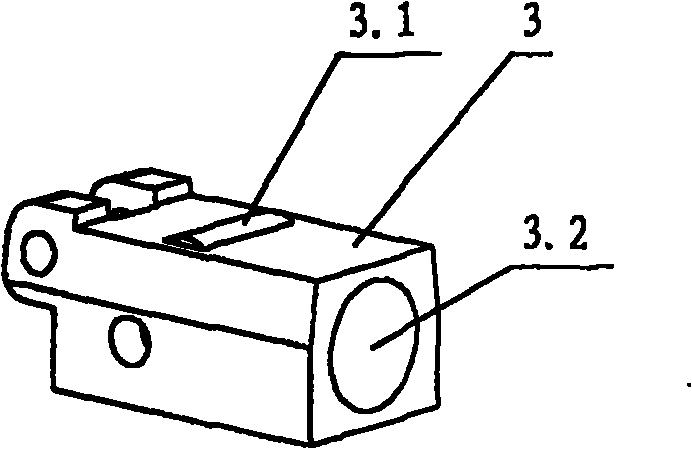
[0042] see figure 1 , Figure 13-Figure 14 and Figure 18-Figure 19 , the panel locking and adjusting device of the drawer with slide rails, including the slide rails connected with the drawer, the drawer panel 24 is connected with the adjustment seat 6 through the left and right two T-shaped connectors 7, the adjustment seat 6 and the slide rail Set in the drawer wall 21, a supporting plate 19 is arranged between the adjusting seat and the slide rail, the adjusting seat is connected with the sliding rail through the supporting plate 19, and the adjusting seat is provided with an up and down adjusting block 12 which can be adjusted up and down respectively and a function The left and right adjustment blocks 8 for left and right adjustment, the connectors 7 are successively connected with the up and down adjustment blocks and the left and right adjustm...


PUM


Abstract

A panel locking and regulating device of a drawer with a dump rail comprises the dump rail which is connected with the drawer; a panel of the drawer is connected with a regulating seat by a connectingpiece, the regulating seat is internally provided with a conduit ferrule, in which the connecting piece can slide. The conduit ferrule is internally provided with a panel locking mechanism which includes an offset cam, one end of which is articulated on the regulating seat and the other end is articulated with a guide block by a connecting rod; one end of a swing rod is articulated on the guide block by a pin roll; a torsion spring is sheathed on the pin roll, and one end of the torsion spring leans against the swing rod and the other end leans against the guide block or the regulating seat;a sliding bush of the guide block is positioned in the regulating seat and the end part of the connecting piece is connected with the other end of the swing rod. The sliding bush of the guide block ispositioned in a location bracket, and the rear part of the guide block is connected with one end of a first spring and the other end of the first spring leans against the location bracket. The invention has the advantages of simple and reasonable structure, flexible operation, high safety, which not only can realize the up and down regulation of the position, but also can realize the left and theright regulation of the position, and the panel can also be separately assembled and disassembled.

Description

technical field [0001] The invention relates to a drawer with a slide rail, in particular to a panel locking and adjusting device for a drawer with a slide rail. Background technique [0002] At present, drawers with slide rails are directly fixed on the inner rails of the slide rails, and the outer rails of the slide rails are fixed on the drawer wallboards, and the drawers move through the slide rails. If the slide rail deviates during installation, it will directly cause the drawer panel to be up, down, left or right, and the drawer cannot be closed. In consideration of sliding safety, the inner and outer rails in the slide rails are not detachable. If the drawer needs to be cleaned, the inner and outer rails need to be disassembled. The disassembly process is quite troublesome. In response to this situation, some manufacturers have made some improvements, such as a drawer rail assembly disclosed in Chinese Patent Document No. CN 200973516Y, which includes an upper rail,...

Claims


Application Information

Patent Timeline
Patent Type & Authority Patents(China)
IPC IPC(8): A47B88/04
Inventor 伍志勇
Owner 伍志勇
Why Eureka
Try Eureka