magnetic lock

A magnetic lock and lock body technology, applied in the field of door and window locks, can solve the problems of reducing the service life of the lock, damage to the user's body, wear and tear of the lock tongue and striker plate, etc., and achieve the effects of prolonging the service life, improving practicability, and facilitating unlocking

Active Publication Date: 2017-12-29
中山市欧柏克五金制品有限公司
View PDF4 Cites 0 Cited by
  • Summary
  • Abstract
  • Description
  • Claims
  • Application Information

AI Technical Summary

Problems solved by technology

[0002] Existing locks, such as: locksets for doors and windows, its structure includes a striker plate, a lock body and a dead bolt, the dead bolt is arranged in the lock body through an elastic mechanism, and the dead bolt is connected with the rotating mechanism in the lock body. , the lock tongue elastically collides with the strike plate through the elastic mechanism, and finally the lock tongue is inserted into the strike plate to complete the door locking operation. However, after many collisions, the lock tongue and the strike plate are easy to cause wear and tear, which greatly reduces the lock service life
[0003] When the existing lock body is unlocked, the handle needs to be pulled hard, and the handle drives the lock tongue to retract into the lock body. The normal state is the state of extending the lock body, and the lock tongue that extends the lock body is easy to scrape with the clothes of the human body, causing damage to the clothes, and even causing damage to the user's body due to the user accidentally touching the lock tongue

Method used


Image

  • magnetic lock
  • magnetic lock
  • magnetic lock

Examples


Embodiment

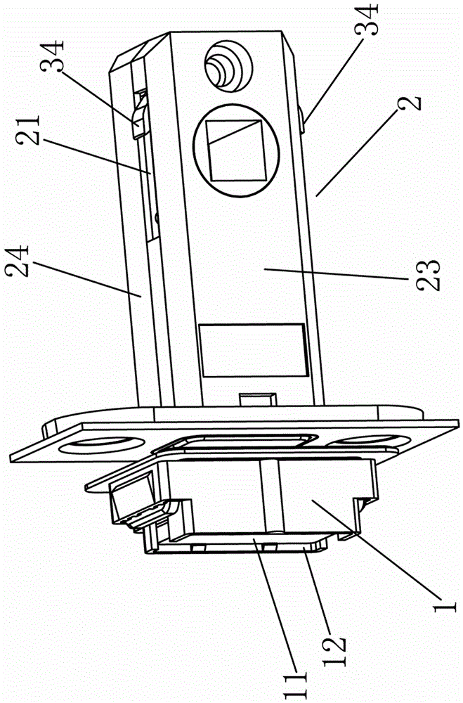
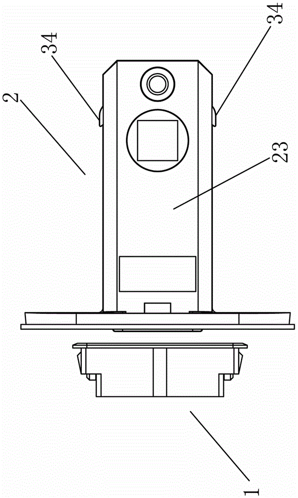
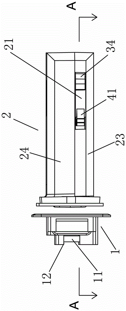
[0027] Example, combined with Figure 1 to Figure 8 As shown, a magnetic lock includes a striker plate 1, a lock body 2, a dead bolt 3 and a handle core 4, the striker plate 1 is installed on the door frame, and the bottom of the striker plate 1 is provided with a first magnet The accommodating cavity 12 , the first magnet 11 is locked in the first magnet accommodating cavity 12 .

[0028] The magnetic lock is installed on the door body corresponding to the position of the strike plate 1. The lock body 2 of the magnetic lock includes a cover 23 and a box body 24. The upper and lower side walls of the cover 23 are provided with chute 21, and the inner cavity of the box body 24 is A second magnet accommodating groove 25 is provided, and the second magnet 22 is clamped in the second magnet accommodating groove 25 , and the cover 23 and the box body 24 are buckled to form the lock body 2 .

[0029] The deadbolt 3 includes a deadbolt head 31 and two legs 32, the deadbolt head 31 i...


PUM


Abstract

A magnetic lock comprises a lock body, a spring bolt and a handle core mark. The spring bolt and the handle core mark are arranged in the lock body. A first magnet is inlaid into a buckle plate. Sliding grooves are formed in the lock body side walls of a lock body device, and a second magnet is arranged at the position, between the spring bolt and the handle core mark, of a lock body inner cavity. The spring bolt comprises a spring bolt head and supporting legs. A third magnet is inlaid into an inner cavity of the spring bolt head. One end of each supporting leg is connected with the spring bolt head. The other end of each supporting leg is bent outwards to form a hook. The hooks extend into the sliding grooves of the lock body, and the spring bolt slides along the sliding grooves. A limiting block is arranged on one side of the handle core mark, the handle core mark is arranged at the position, between the sliding grooves in the two sides of the lock body, of the lock body inner cavity, and the limiting block rotates along with the handle core mark to adjust the sliding distance of the spring bolt in the lock body. Due to the fact that attraction of magnetic force between the magnets is utilized during opening or closing of the lock body, the force of people for wrenching a handle is reduced during unlocking, people only need to push the handle slightly, and the spring bolt can retract into the lock body; and therefore, people can open the lock conveniently, and the practicality of the magnetic lock is improved.

Description

technical field [0001] The invention relates to a door and window lock, in particular to a magnetic door and window lock. Background technique [0002] Existing locks, such as: locksets for doors and windows, its structure includes a striker plate, a lock body and a dead bolt, the dead bolt is arranged in the lock body through an elastic mechanism, and the dead bolt is connected with the rotating mechanism in the lock body. , the lock tongue elastically collides with the strike plate through the elastic mechanism, and finally the lock tongue is inserted into the strike plate to complete the door locking operation. However, after many collisions, the lock tongue and the strike plate are easy to cause wear and tear, which greatly reduces the lock service life. [0003] When the existing lock body is unlocked, the handle needs to be pulled hard, and the handle drives the lock tongue to retract into the lock body. The normal state of the lock body is the state of extending the...

Claims


Application Information

Patent Timeline
Patent Type & Authority Patents(China)
IPC IPC(8): E05B47/00
CPCE05B47/004
Inventor 徐志克
Owner 中山市欧柏克五金制品有限公司
Why Eureka
Try Eureka