Locking mechanism of connector

A locking mechanism and connector technology, which is applied in the direction of connection, parts of the connection device, electrical components, etc., can solve problems such as difficulty in disconnecting the connector, and achieve the effect of improving operability

Inactive Publication Date: 2008-07-23
YAZAKI CORP
View PDF2 Cites 6 Cited by
  • Summary
  • Abstract
  • Description
  • Claims
  • Application Information

AI Technical Summary

Problems solved by technology

Therefore, in the case where there is no space for the finger to insert the lock release operation, etc., since the above

Method used


Image

  • Locking mechanism of connector
  • Locking mechanism of connector
  • Locking mechanism of connector

Examples


Embodiment Construction

[0040] Embodiments of the present invention will be described below with reference to the drawings.

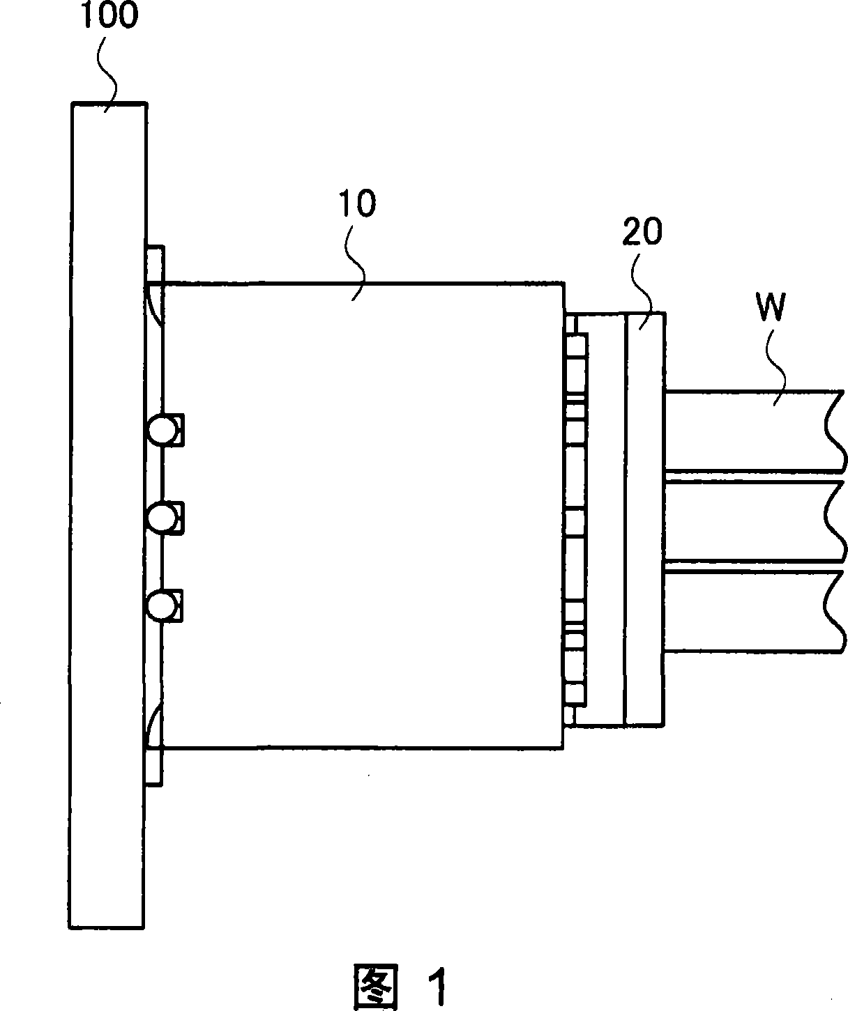
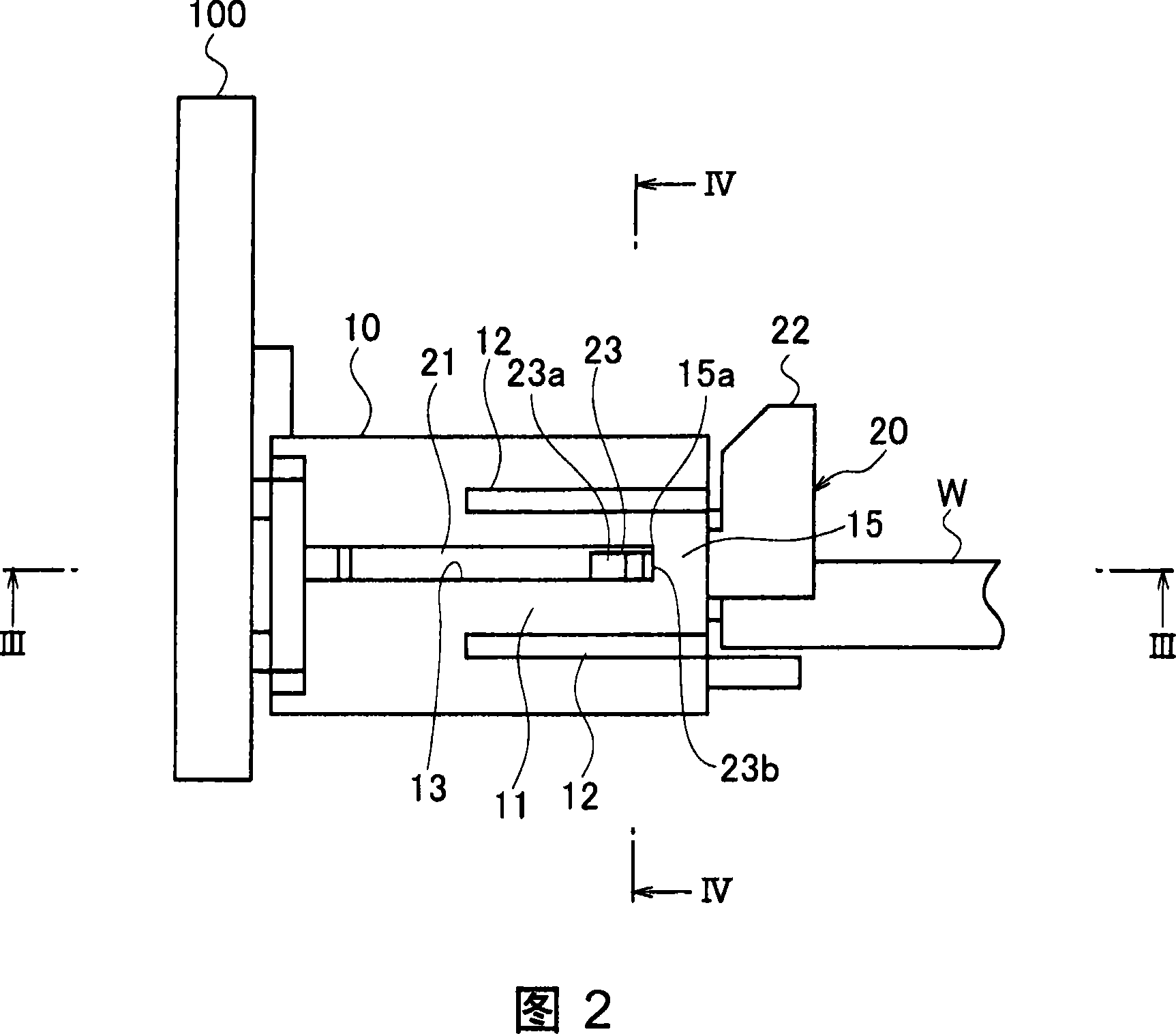
[0041] In FIGS. 1 to 10, the connector consists of a receptacle connector (hereinafter referred to as the first connector) 10 fixed on the substrate 100, and a plug connector (hereinafter referred to as the first connector) that is plugged into the receptacle connector 10. for the second connector). The first connector 10 is an inner connector, and the second connector 20 is an outer connector fitted inside the first connector 10 .

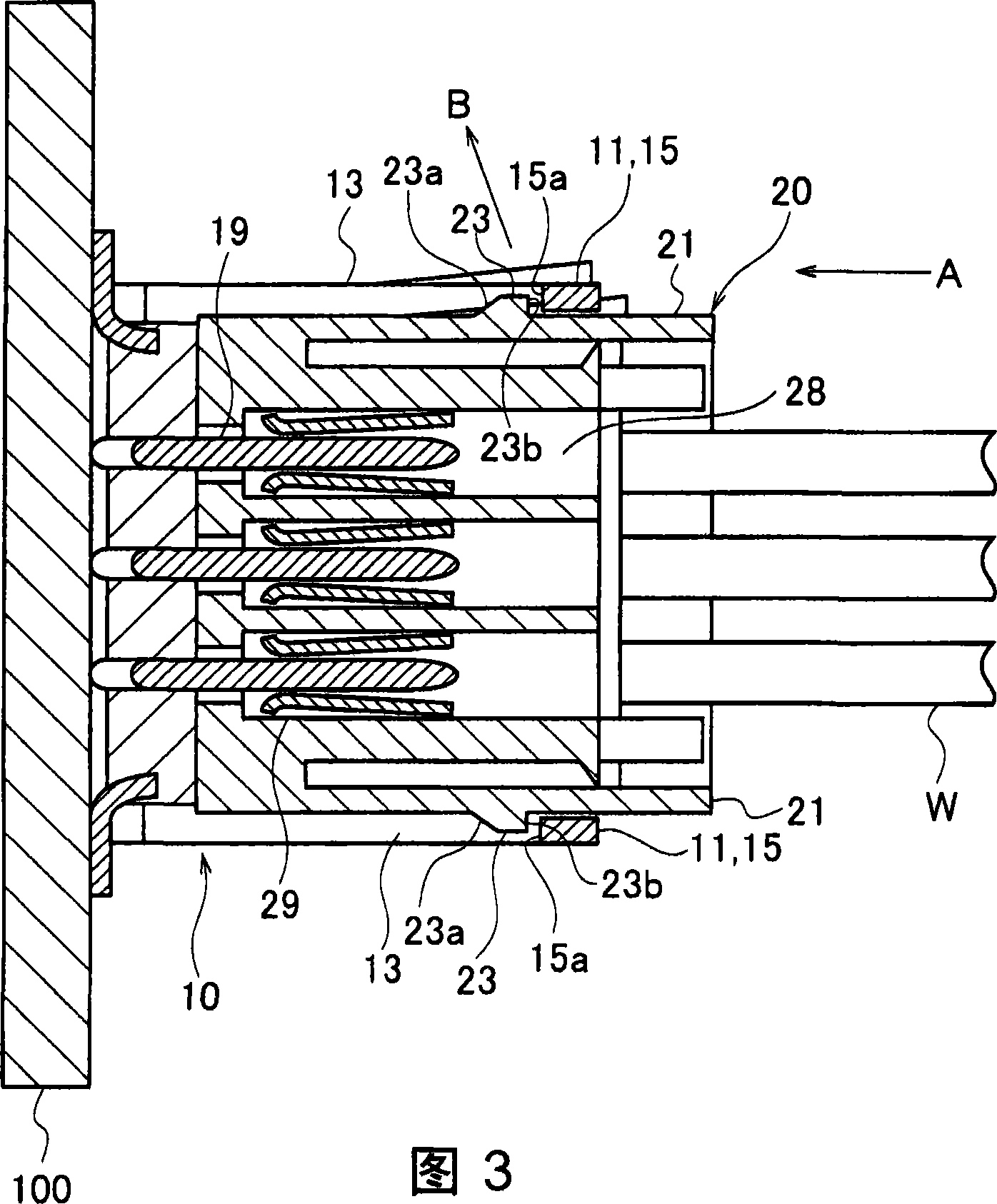
[0042] In the fitting hole 18 of the housing of the first connector 10, the front ends of a plurality of first contact members 19 protrude parallel to the connector fitting direction so as to be able to fit with the contact members on the other side. . In addition, in a contact mounting hole 28 provided in the housing of the second connector 20, a second contact 29 at the front end of each electric wire W drawn out from the rear of the housing i...


PUM


Abstract

A locking mechanism of connector comprises a first and second locking part (15, 23). The first and second locking part (15, 23) are respectively formed on the shells of the first and second connector (10, 20) intercalated with each other. The first and second connectors are intercalated with each other at the right position to be locked at intercalating status. A depressed part (14) or groove for keeping the disarm state is formed on the inner face of the first connector. When the second locking part moves to the position for releasing the intercalating relation with the first locking part, the second locking part is kept at the position.

Description

technical field [0001] The present invention relates to a lock mechanism of a connector, which enables a lock release operation and a connector pull-out operation to be performed separately when the connector is disengaged. Background technique [0002] For example, in the connectors used in the connection of wiring such as automobiles, there is a function of fitting the outer and inner connectors together when they are fitted in the normal (standard, Japanese: "regular") position. A locking mechanism that maintains a locked state. [0003] For connectors with a common locking mechanism, when the outer and inner connectors are disengaged, the disengagement of the connector is realized by simultaneously performing the operation of pulling out the connector while performing the unlocking operation (see Patent Document 1 ). [0004] In addition, there is also a connector locking mechanism that enables the connector to be pulled out while performing a lock release operation us...

Claims


Application Information

Patent Timeline
IPC IPC(8): H01R13/627H01R13/639
Inventor 村山龙介
Owner YAZAKI CORP
Why Eureka
Try Eureka