
Splicing apparatus for splicing curtain material

A splicing device and cord fabric technology, which can be used in application, thin material processing, winding strips, etc., can solve problems such as cost

Active Publication Date: 2014-12-17
KARL EUGEN FISCHER GMBH
View PDF7 Cites 4 Cited by
  • Summary
  • Abstract
  • Description
  • Claims
  • Application Information

AI Technical Summary

Problems solved by technology

Correspondingly, maintenance, repairs and possibly replacement of the pressing cylinders are always associated with relatively high outlay, which correspondingly results in long downtimes of the splicing device.

Method used


Image

  • Splicing apparatus for splicing curtain material
  • Splicing apparatus for splicing curtain material
  • Splicing apparatus for splicing curtain material

Examples


Embodiment Construction

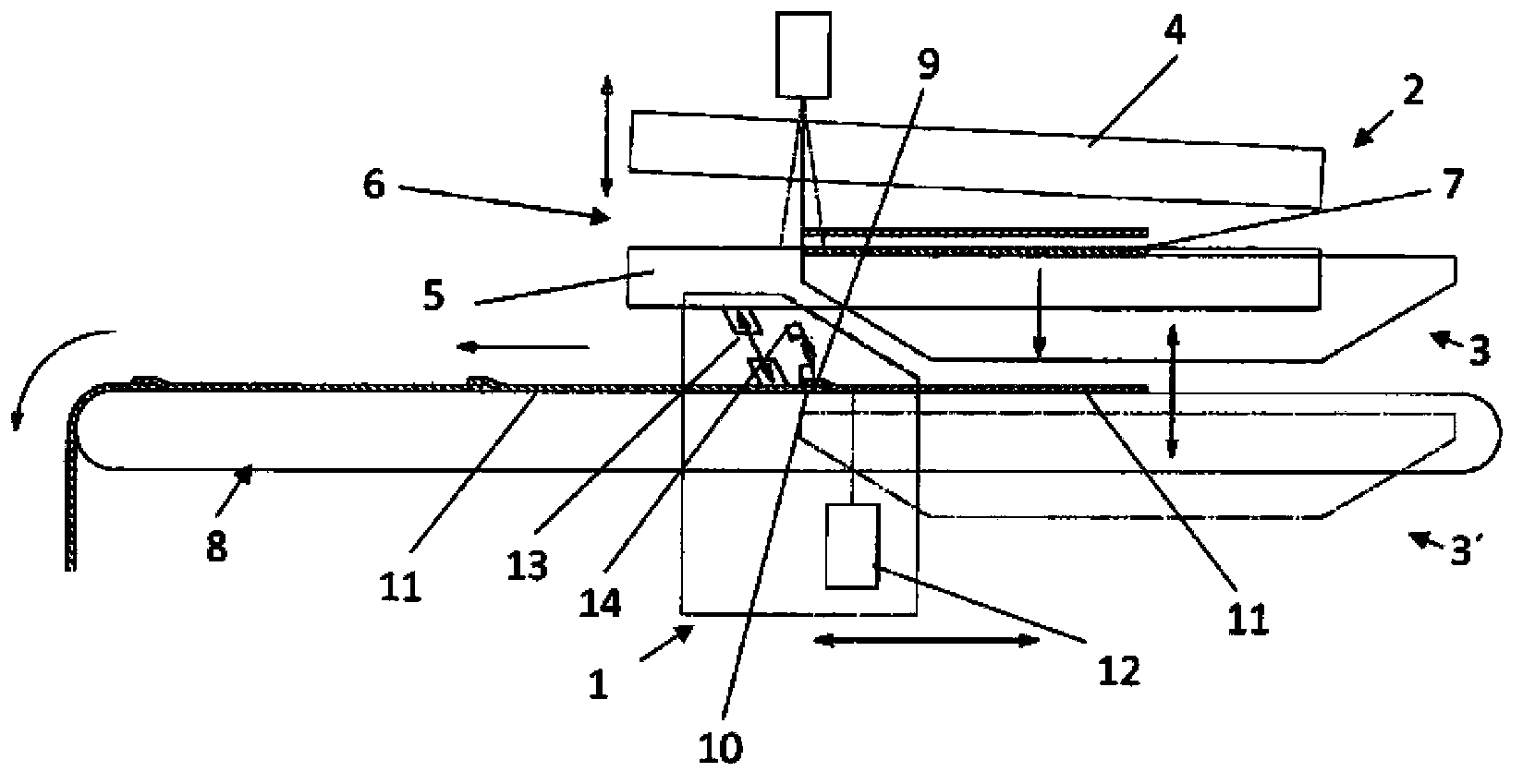
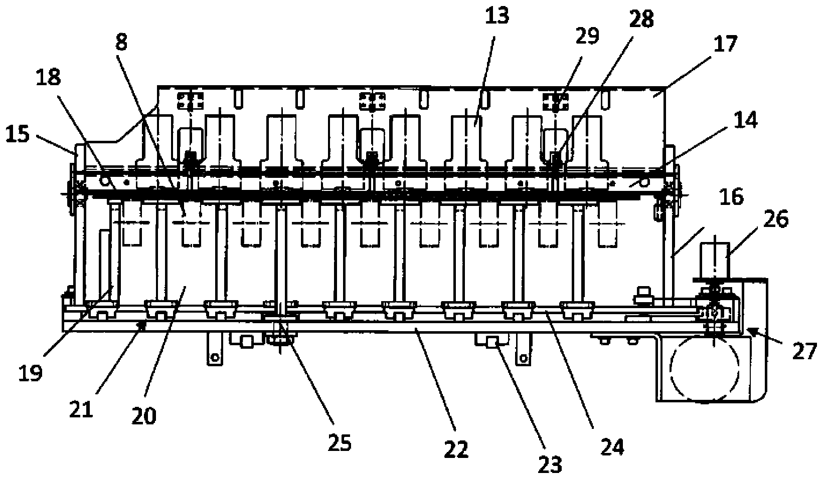
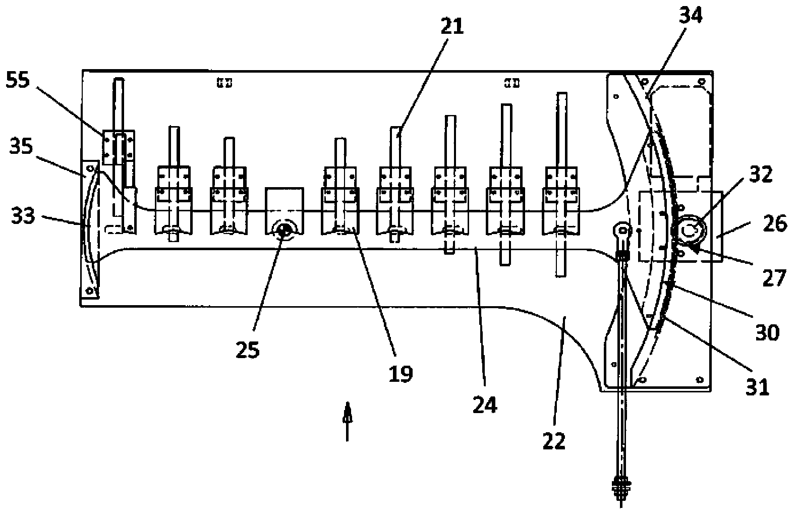
[0043] exist figure 1 The principle for integrating the splicing device 1 into a cutting device for strips of ply material, in particular with textile and / or steel wires, is shown in . The splicing device 1 is designed here as a unit with a cutting machine 2 and a liftable frame 3 that can move up and down.

[0044] The cutter 2 has an upper blade 4 and a lower blade 5 , between which a knife edge 6 is formed, through which the material web is guided through, for example by means of a pulling device. By closing said knife edge 6 in such a way that eg the upper blade 4 is guided downwards, the strip section is cut from the material strip. These strip sections are supported during cutting by the liftable frame 3 , here in its extraction position.

[0045] After the cutting process has ended, the liftable frame 3 is moved vertically downwards into its output position, wherein it transfers the newly cut strip section 7 to the conveyor belt 8 . The conveyor belts 8 are arranged ...


PUM


Abstract

A splicing apparatus (1) for splicing tape sections (7, 11) of a material tap especially prepared from a curtain material. The curtain material is reinforced by textile filament and / or steel wire. The splicing apparatus has a splicing pressure plate (14) which is supported in a manner of pivoting parallel to the longitudinal axis. The tape sections (7, 11) can penetrate and guide between a lower side face and an abutting face of the splicing pressure plate (14) and the splicing pressure plate (14) can manipulate with a hold-down cylinder (40) facing the abutting face to splice and connected the two tape sections (7, 11). The hold-down cylinder (40) is arranged between a transverse joint device (17) and the splicing pressure plate (14). In order to realize simple approaching for maintenance and replacement, an end portion of the hold-down cylinder (40), far away from the splicing pressure plate (14), is fastened on the transverse joint device (17), and the other end portion of the hold-down cylinder is fastened on a fastening section (28) at the front side of the splicing pressure plate (14).

Description

technical field [0001] The invention relates to a splicing device for splicing strip sections of a material web, in particular made of a ply material reinforced with textile and / or steel wires, the splicing device having a splicing platen , the splicing platen extends in the machine transverse direction and is supported in a pivotable manner parallel to its longitudinal axis, wherein the belt section can be guided through between the underside and the abutment surface of the splicing platen and thus The splice pressure plate can be manipulated towards the contact surface via a pressure cylinder for producing a splice connection between the two belt sections, wherein the pressure cylinder is arranged between the transverse connecting device and the splice pressure plate. Background technique [0002] Such splicing devices are used to splice an edge of a previously cut strip section in a cutting machine with an edge of a subsequent strip section and thus produce a new endless ...

Claims


Application Information

Patent Timeline
Patent Type & Authority Applications(China)
IPC IPC(8): B29D30/38B29D30/46B65H20/10B65G15/60B65H35/00
Inventor 乌多·舒尔茨瓦尔特·弗利格
Owner KARL EUGEN FISCHER GMBH
Learn More