Torque transmission arrangement for a motor vehicle

a transmission arrangement and motor vehicle technology, applied in the direction of couplings, belts/chains/gearrings, differential gearings, etc., can solve the problems of easy errors in the actuation of the shift clutch, difficult installation, etc., to reduce the introduction of heat, improve the shift force transmission, and reduce wear.

Active Publication Date: 2014-06-12
DR ING H C F PORSCHE AG
View PDF10 Cites 4 Cited by
  • Summary
  • Abstract
  • Description
  • Claims
  • Application Information

AI Technical Summary

Benefits of technology

[0007]This object is achieved according to the invention in that the axial bearing arrangement has a rolling bearing and a bearing disk element directed toward the first clutch element. The rolling bearing with a corresponding bearing disk element surprisingly provides a substantially improvement in the shift force transmission. The shift actuation now proceeds in a completely play-free manner, and the introduction of heat is minimized. Furthermore, there result further advantages in terms of a lower wear and an improved drag torque. The rolling bearing preferably has a stop disk on the side opposite the bearing disk element. The first clutch element preferably is under prestress via a spring to ensure a reliable disengagement of the first clutch in the non-actuated state. A sensor with a transducer element preferably is provided for reliably monitoring the engaging and disengaging operation. The transducer element preferably is arranged between the axial bearing arrangement and the first clutch for reliably monitoring the engaging and disengaging operation. The transducer element preferably is a sensor disk that centers the bearing disk element via a centering surface. Alternatively, the sensor disk and the bearing disk element may be designed in one piece.

Problems solved by technology

Installation is difficult due to the small installation space and the demands for a low weight.
However, these axial bearings have the disadvantage that they have a certain air gap in the non-actuated or non-engaged state, with the result that the actuation of the shift clutch is prone to errors.

Method used


Image

  • Torque transmission arrangement for a motor vehicle
  • Torque transmission arrangement for a motor vehicle
  • Torque transmission arrangement for a motor vehicle

Examples


Embodiment Construction

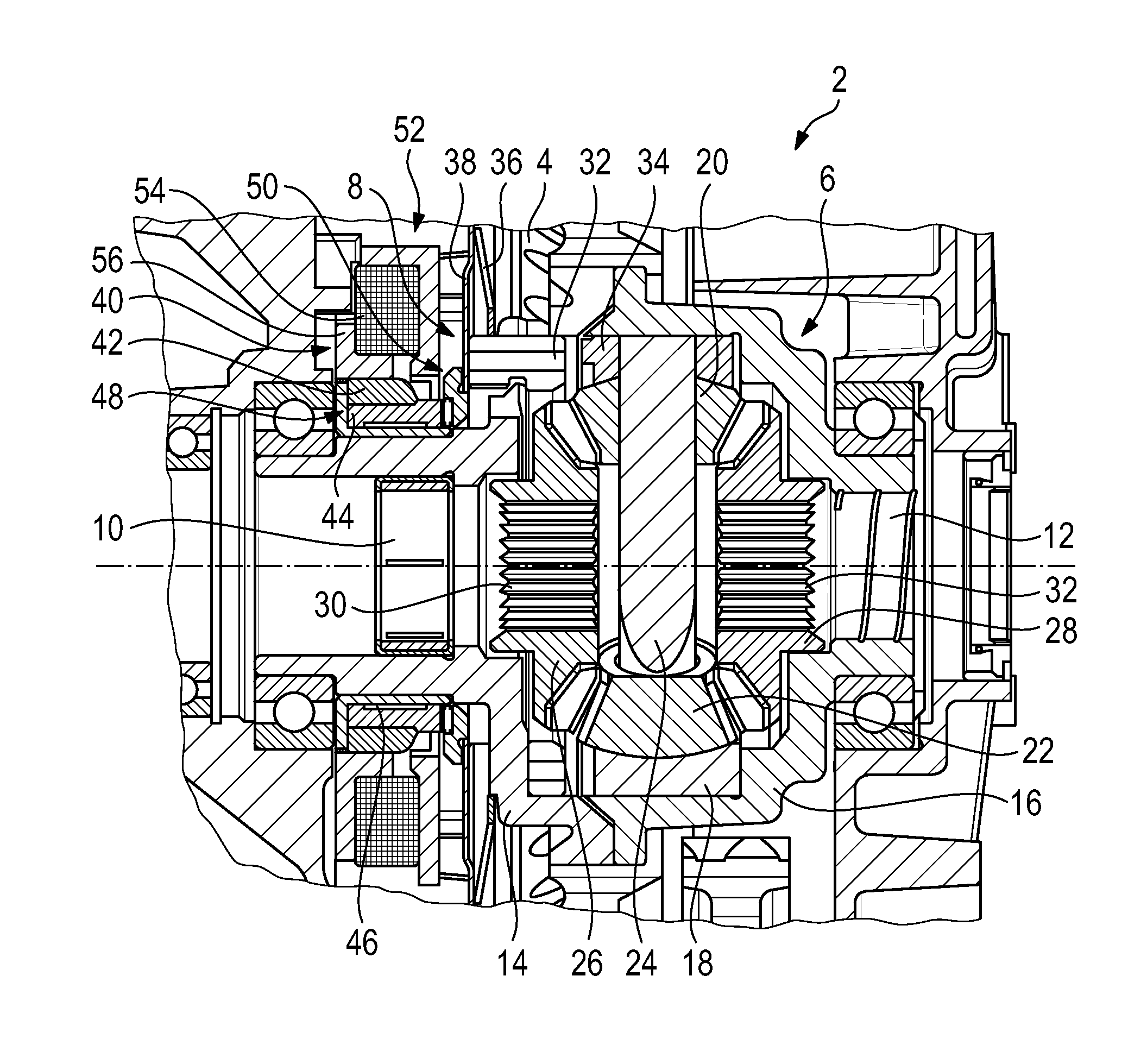
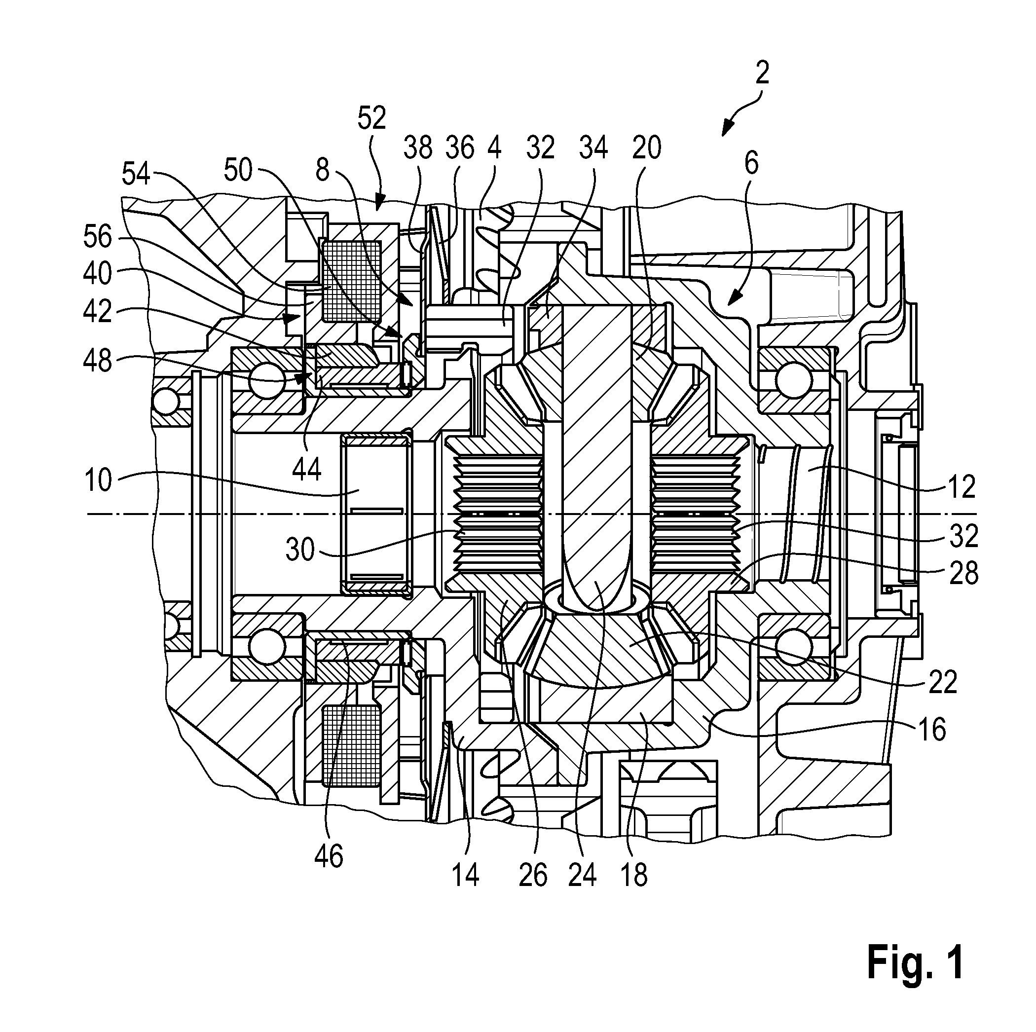
[0014]FIG. 1 shows a torque transmission arrangement 2 according to the invention for a motor vehicle. The torque transmission arrangement 2 has a drive element 4 in the form of a drive gear from which a torque is transmitted via a transmission 6 and via a shift clutch arrangement 8 to output elements. The output elements may be axle side shafts that are connected in a known manner to drive wheels and that are mounted via constant-velocity joints 10, 12 in the torque transmission arrangement 2.

[0015]The transmission 6 is a differential transmission known per se and is therefore described only by way of example. The differential transmission 6 has a two-part differential cage 14, 16 that is connected in a rotationally fixed manner to the drive gear 4. Furthermore, a differential carrier 18 is mounted slidably in the differential cage part 16. Two compensating gears 20, 22 are mounted rotatably on a journal 24 that is connected in a rotationally fixed manner to the differential carrie...


PUM


Abstract

A torque transmission arrangement for a motor vehicle has a drive element (4) and at least one output element connected to one another via a transmission (6) and a shift clutch arrangement (8). The shift clutch arrangement (8) has an actuator (40) that moves a first clutch element (32) axially in the direction of a second clutch element (34) via a displacement element (42, 44) in such a way that a positive connection can be produced between the drive element (4) and the output element. The first clutch element (32) bears via an axial bearing arrangement (50) against the displacement element (42, 44) as seen in the axial direction. The axial bearing arrangement (50) has a rolling bearing (58) and a bearing disk element (62) directed toward the first clutch element (32).

Description

CROSS REFERENCE TO RELATED APPLICATION[0001]This application claims priority under 35 USC 119 to German Patent Appl. No. 10 2012 111 971.6 filed on Dec. 7, 2012, the entire disclosure of which is incorporated herein by reference.BACKGROUND[0002]1. Field of the Invention[0003]The invention relates to a torque transmission arrangement for a motor vehicle having a drive element and at least one output element that are connected to one another via a transmission and a shift clutch arrangement. The shift clutch arrangement has an actuator that moves a first clutch element axially in the direction of a second clutch element via a displacement element in such a way that a positive connection can be produced between the drive element and the output element. The first clutch element bears via an axial bearing arrangement against the displacement element as seen in the axial direction.[0004]2. Description of the Related Art[0005]Torque transmission arrangements are well known from the prior a...

Claims


Application Information

Patent Timeline
Patent Type & Authority Applications(United States)
IPC IPC(8): F16D11/14
CPCF16D11/14F16D11/10F16D27/118F16D2300/14F16D2300/18F16H48/08F16H48/24F16H2048/346
Inventor KNOBLAUCH, DANIELSINGER, SIMON
Owner DR ING H C F PORSCHE AG
Why Eureka
Try Eureka