Method and system for variable cam timing device

a technology of variable cam timing and cam timing, which is applied in the direction of valve details, valve arrangements, valve drives, etc., can solve the problems of affecting the performance of the engine, affecting and affecting the operation of the engine. achieve the effect of improving the fuel economy and emissions performance of the vehicl

Active Publication Date: 2017-03-21
FORD GLOBAL TECH LLC
View PDF11 Cites 4 Cited by
  • Summary
  • Abstract
  • Description
  • Claims
  • Application Information

AI Technical Summary

Benefits of technology

[0002]Internal combustion engines may use variable cam timing (VCT) to improve fuel economy and emissions performance of a vehicle. The VCT device may include a vane type cam phaser that is controlled by an electromechanically actuated spool valve. The spool valve may direct flow of a hydraulic fluid, such as oil, from one side of the vane to the other, such as from a retard side to an advance side. The VCT device may include more than one oil circuit connecting one side of the vane to the other through which the flow of a hydraulic fluid may be directed. The phaser may be oil pressure actuated, wherein the actuation of the phaser is dependent on oil pressure in the circuit. Alternatively, the phaser may be cam torque actuated wherein the actuation of the phaser is dependent on torque generated during cam actuation.
[0005]In one example, the issues described above may be addressed by a method, comprising: in response to a command for phasing a cam torque actuated variable cam timing phaser from a locked position, jumping a spool valve from a detent region to outside a null region, and ramping the spool valve through the null region while monitoring for cam timing movement away from a locked position. In this way, the locking pin may reliably disengage before a position of the cam phaser is changed, thereby reducing side-loading of the locking pin.
[0007]In this way, the locking pin of a cam phaser may be disengaged only when the duty cycle is commanding minimal amounts of phase adjustment, if any amount at all. Additionally, the locking pin is ensured to be disengaged before the duty cycle resumes normal phasing operations. Thus reliable disengagement of the locking pin is achieved and side-loading due to phase adjustments is reduced during disengagement. Overall, valve timing control is improved.

Problems solved by technology

Additionally, fluid is blocked from flowing through the phasing circuit lines.
However, the inventors herein have identified potential issues with such a VCT system.
This scenario may prevent or severely delay the execution of phasing requests, which may result in degraded engine performance.
In addition, undue stress may be introduced to the locking machinery.

Method used


Image

  • Method and system for variable cam timing device
  • Method and system for variable cam timing device
  • Method and system for variable cam timing device

Examples


Embodiment Construction

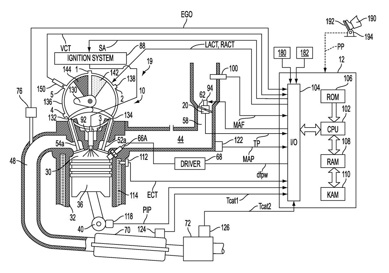
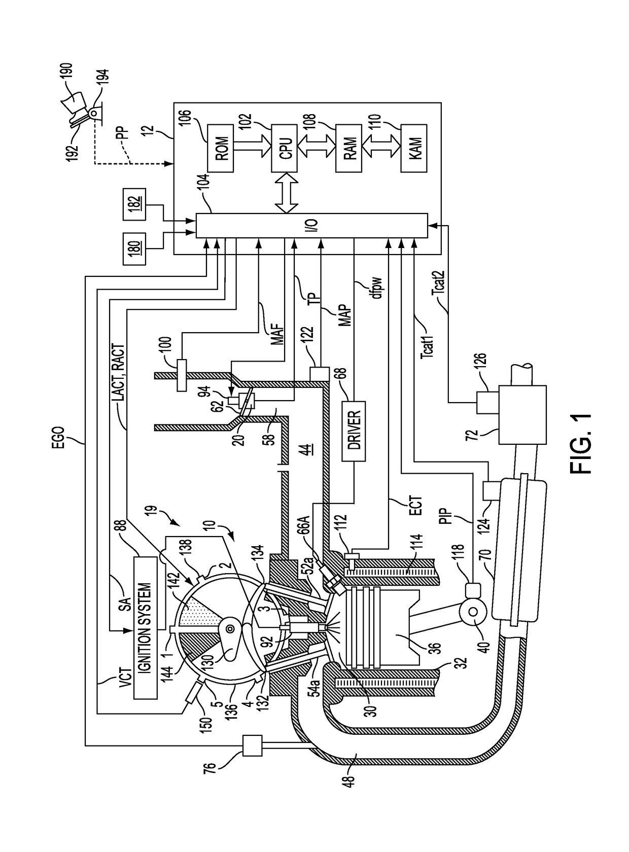
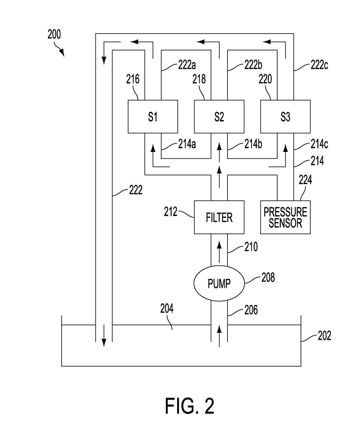
[0025]The following description relates to systems and methods for controlling an engine of a vehicle, the engine having a variable cylinder valve system, such as the variable cam timing (VCT) of FIGS. 1-3. An engine controller may be configured to adjust a duty cycle commanded to a spool valve of a VCT phaser to adjust the phaser position, as discussed at FIGS. 4-6. During conditions when the phaser is to be unlocked and moved, the controller may select a method for robustly unlocking the phaser while reducing phasing errors, such as depicted at FIGS. 7A-C and 8A-B. The controller may likewise adjust a spool valve command to enable accurate locking of the phaser in a position, as discussed at FIGS. 9-12. The controller may also intermittently map the spool valve so as to adaptively learn spool valve regions and accordingly update duty cycle commands for phaser positioning, as elaborated at FIGS. 13-14. Further still, the controller may use camshaft torsion variations to identify VC...


PUM


Abstract

Methods and systems are described for an engine with a cam torque actuated variable cam timing phaser. Phaser positioning control is improved by reducing inaccuracies resulting from inadvertent spool valve and / or phaser movement when the spool valve is commanded between regions. In addition, improved spool valve mapping is used to render phaser commands more consistent and robust.

Description

FIELD[0001]The present application relates to methods for operating an engine with variable cam timing (VCT).BACKGROUND AND SUMMARY[0002]Internal combustion engines may use variable cam timing (VCT) to improve fuel economy and emissions performance of a vehicle. The VCT device may include a vane type cam phaser that is controlled by an electromechanically actuated spool valve. The spool valve may direct flow of a hydraulic fluid, such as oil, from one side of the vane to the other, such as from a retard side to an advance side. The VCT device may include more than one oil circuit connecting one side of the vane to the other through which the flow of a hydraulic fluid may be directed. The phaser may be oil pressure actuated, wherein the actuation of the phaser is dependent on oil pressure in the circuit. Alternatively, the phaser may be cam torque actuated wherein the actuation of the phaser is dependent on torque generated during cam actuation.[0003]One example of a cam torque actua...

Claims


Application Information

Patent Timeline
Patent Type & Authority Patents(United States)
IPC IPC(8): F01L1/34F01L1/344
CPCF01L1/344F01L1/08F01L1/34409F01L2001/3443F01L2001/34459F01L2001/34463F01L2250/02F01L2250/04F01L2250/06F01L2800/01F01L2800/02F01L2800/03F01L1/3442F01L1/047F01L2001/34426F01L2001/3444F01L2001/34453
Inventor PIETRZYK, PAUL A.BADILLO, EDROLLINGER, JOHN ERIC
Owner FORD GLOBAL TECH LLC
Why Eureka
Try Eureka