Connection device for connecting conductor end

A technology for connecting equipment and connecting conductors, applied in the direction of connection, conductive connection, electrical component connection, etc., can solve problems such as difficult manipulation

Active Publication Date: 2020-07-28
WEIDMULLER INTERFACE GMBH & CO KG
View PDF8 Cites 3 Cited by
  • Summary
  • Abstract
  • Description
  • Claims
  • Application Information

AI Technical Summary

Problems solved by technology

However, the known connection devices are difficult to handle precisely when contacting conductors of larger diameters, both in terms of their operation and their structural configuration, and therefore require improvement.

Method used


Image

  • Connection device for connecting conductor end
  • Connection device for connecting conductor end
  • Connection device for connecting conductor end

Examples


Embodiment Construction

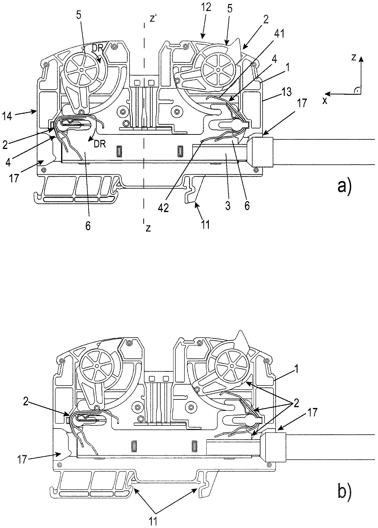
[0031] For simplicity, in figure 1 The Cartesian coordinate system X / Z is marked in , where the direction perpendicular to the paper plane is marked as "Y direction". The conductor insertion direction is marked below as "X direction".

[0032] figure 1 The housing 1 is shown, which is designed here as a clamping housing. One or more (here two) connecting devices 2 for connecting corresponding conductor ends 3 are arranged in the housing. here, in figure 1 Only one of these conductor ends 3 is shown in . The conductor end 3 can be a (preferably de-insulated) single or multi-conductor or stranded conductor or can be, for example, a crimped wire end made of a material that conducts electricity well, such as copper.

[0033] The housing 1 is made of an electrically insulating material, in particular a non-conductive plastic. The housing 1 is designed here in the shape of a plate and is preferably arranged perpendicular to the conductor insertion direction in the Y direction....


PUM


Abstract

Connection device for connecting a conductor end (3), which has a housing (1) and, in the housing (1), a busbar portion (6), a clamping spring arrangement (4) and a rotary lever arrangement (5), wherein the clamping spring arrangement (4) can be rotated, with the aid of the rotary lever arrangement (5), from an open position into a contact position in which the conductor end (3) is contacted, wherein the rotary lever arrangement (5) has a rotary lever element (50) which is mounted in the housing (1) so as to be rotatable in or on a preferably central portion (500) and which has the axis of rotation (D2), and wherein the rotary lever element (50) has an eccentric portion (502) which has a control cam (503) along which the clamping spring arrangement (4) slides during a movement into the endcontact position, wherein the eccentric portion (502) engages by way of a guide means, such as by way of a projection or a pin (504) inserted therein or the like, into a slotted link (18) of the housing (1), and wherein a clamping and / or latching means are or is formed on the eccentric portion (502), and wherein the slotted link (18) of the housing (1) is aligned with a slotted link (60) in the busbar portion (6), in which the fixing position for the clamping and / or latching means is formed.

Description

technical field [0001] The invention relates to a connecting device for connecting conductor ends according to the preamble of claim 1 . Background technique [0002] Such connecting devices are known from the prior art. However, the known connecting devices are difficult to handle with regard to their handling and their structural design precisely when contacting conductors with larger diameters and therefore require improvement. Contents of the invention [0003] Against this background, the object of the present invention is to provide a connection device which is improved in terms of operation and structural construction. [0004] The present invention achieves the object through the technical solution of claim 1 . [0005] The invention provides a connecting device for connecting conductor ends, which has a housing and a busbar section, a clamping spring arrangement and a torsion bar arrangement in the housing, wherein the clamping The spring device can be pivoted ...

Claims


Application Information

Patent Timeline
Patent Type & Authority Applications(China)
IPC IPC(8): H01R4/48H01R9/26
CPCH01R9/26H01R4/4809H01R4/48365H01R11/09
Inventor K·斯特杰帕诺维特S·费林C·克拉森M·瓦尔德霍夫
Owner WEIDMULLER INTERFACE GMBH & CO KG
Why Eureka
Try Eureka