Steam turbine rotor blade assembly

a technology of steam turbines and rotor blades, which is applied in the direction of liquid fuel engines, vessel construction, marine propulsion, etc., to achieve the effects of reducing stress, enhancing structural damping, and increasing accuracy of positioning the rotor blade and the rotor blad

Active Publication Date: 2009-04-16
MITSUBISHI POWER LTD
View PDF5 Cites 34 Cited by
  • Summary
  • Abstract
  • Description
  • Claims
  • Application Information

AI Technical Summary

Benefits of technology

[0008]It is an object of the present invention to provided a steam turbine rotor blade assembly that controls gap tolerance between a shroud surface and a bar-like member to ensure structural damping between the bar-like member and a shroud for reducing vibratory stress, in a structure of inserting a shim or the bar-like member such as a pin or the like between the shroud surfaces.
[0020]According to the present invention, since the pin is provided between the blade root and the root attachment, accuracy of positioning the rotor blade and the rotor is increased. Thus, the gap tolerance between the shroud surface and the bar-like member can be controlled to bring the shroud surface and the bar-like member into reliable contact with each other.
[0021]Consequently, the contact area between the shroud and the bar-like member can be increased to enhance structural damping, thereby reducing stress relative to a vibratory load.

Problems solved by technology

Therefore, there are various contrives in the structures, particularly, in an implanted portion of an airfoil and in a shroud disposed at a tip of the airfoil.

Method used


Image

  • Steam turbine rotor blade assembly
  • Steam turbine rotor blade assembly
  • Steam turbine rotor blade assembly

Examples


first embodiment

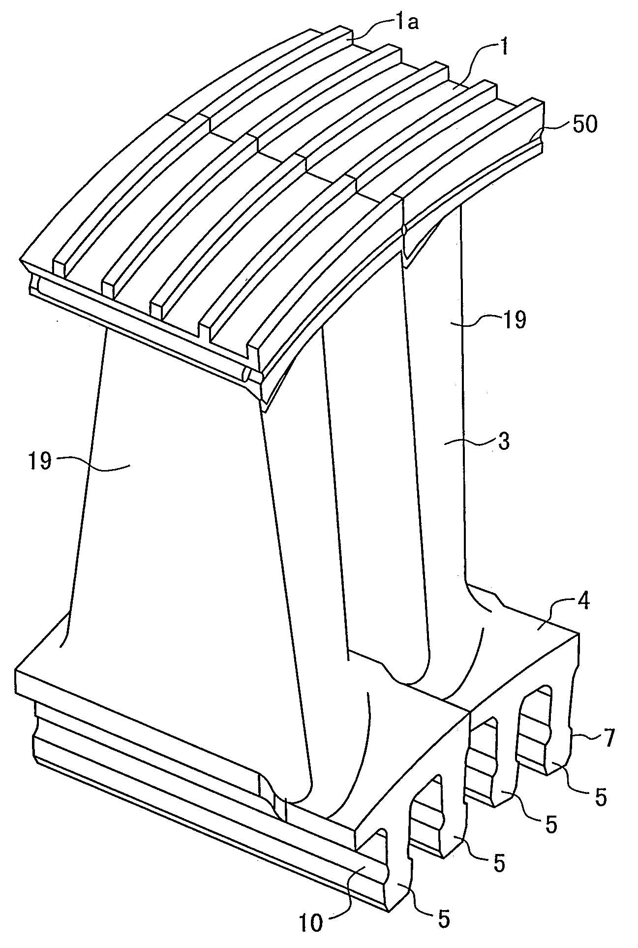
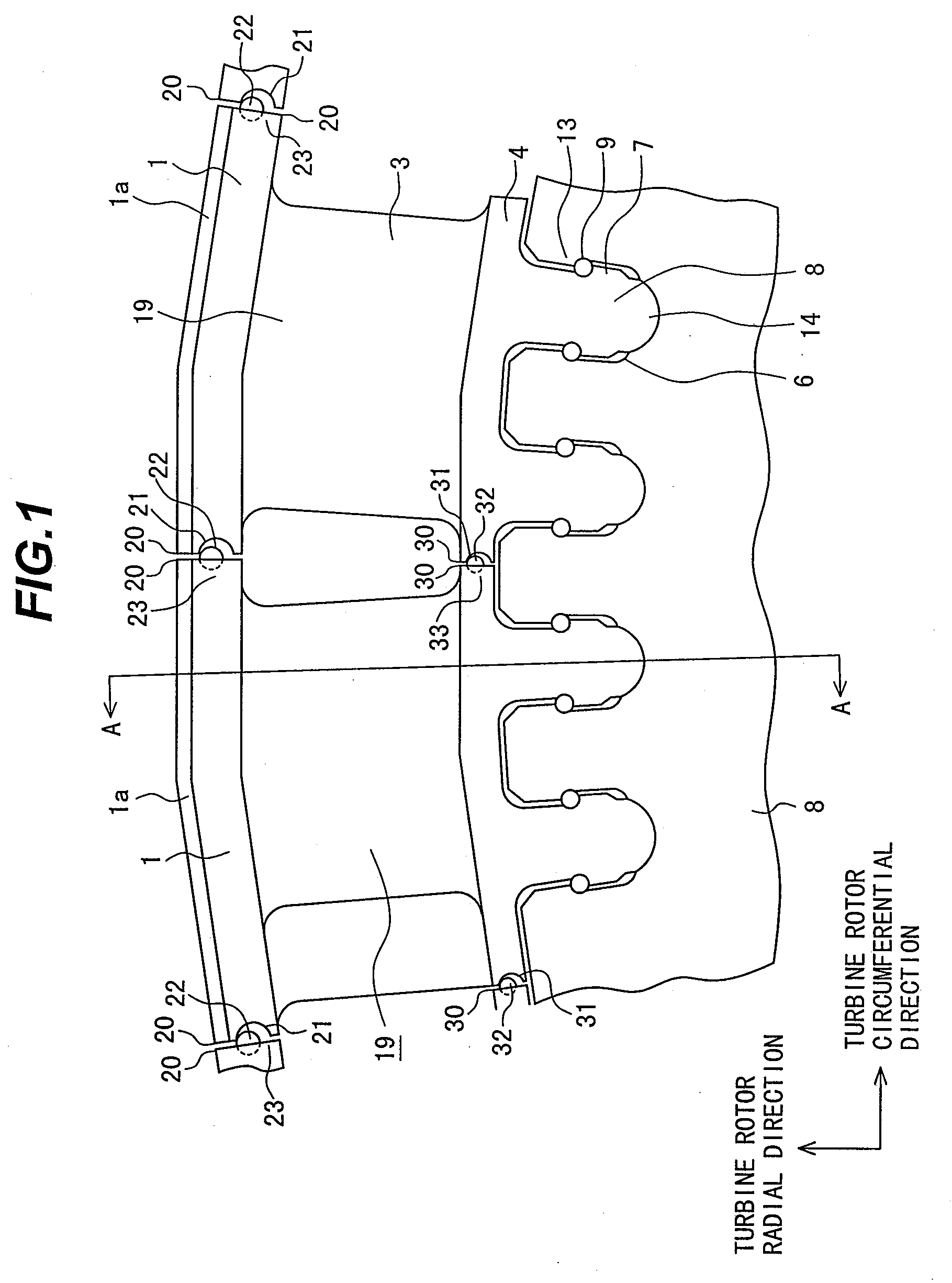
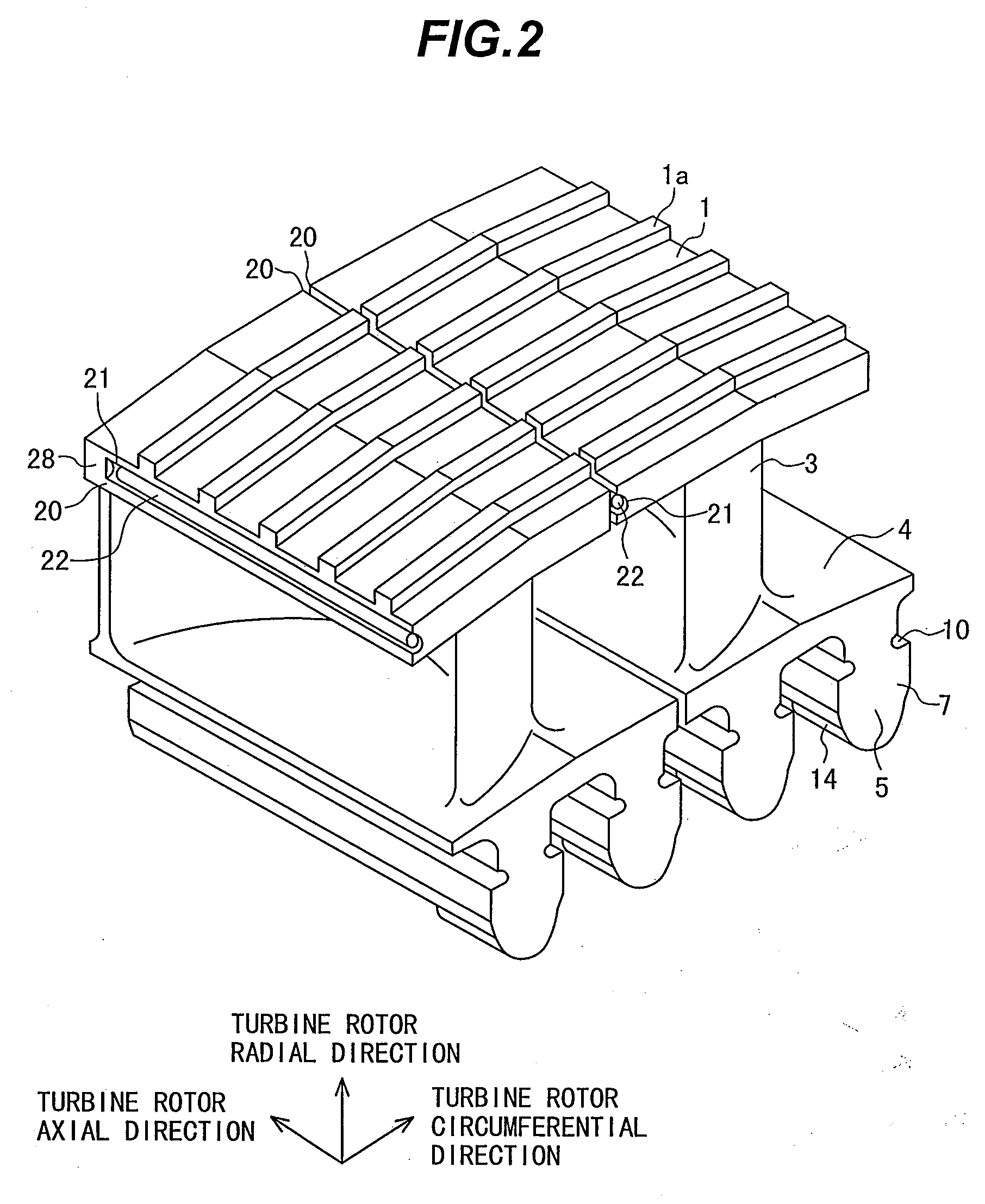
[0032]FIG. 1 is a front view of a steam turbine rotor blade according to an embodiment of the present invention as viewed from a turbine rotor axial direction. FIG. 2 is a perspective view of the steam turbine rotor blade.

[0033]A steam turbine rotor blade 19 of the first embodiment includes an airfoil 3; a shroud 1 provided at a tip of the airfoil 3; a labyrinth seal 1a disposed at a tip of the shroud 1; blade roots 5 each projecting toward the radially inner circumferential side of a turbine rotor 8 and fitted to a root attachment 6 provided on the outer circumference of a turbine rotor; and a platform 4 provided between the airfoil 3 and the blade roots 5. The rotor blade 19 is implanted into the root attachments 6 in the axial direction of the turbine rotor.

[0034]The blade root 5 includes a blade root hook 7, and the root attachment 6 of the turbine rotor includes a root attachment hook 13. A bore is provided at a contact portion of the blade root hook 7 of the blade root 5 and t...


PUM


Abstract

The present invention is a steam turbine rotor blade assembly including: an airfoil; a shroud provided at a tip of the airfoil; a blade root (dovetail) projecting toward a radially internal circumferential side of a turbine rotor and fitted to a root attachment provided on an outer circumferential portion of the turbine rotor; a platform provided between the airfoil and the blade root; a pin provided between the blade root and the root attachment; a bore formed between respective surfaces of the shrouds facing each other and included in the respective adjacent rotor blades; and a bar-like member provided in the bore.

Description

BACKGROUND OF THE INVENTION[0001]1. Field of the Invention[0002]The present invention relates to a steam turbine rotor blade and an assembly using the same.[0003]2. Description of the Related Art[0004]Steam turbine rotor blades are subjected to a large centrifugal force resulting from rotation of a rotor and to a vibratory load due to steam. Therefore, there are various contrives in the structures, particularly, in an implanted portion of an airfoil and in a shroud disposed at a tip of the airfoil.[0005]More specifically, to reduce response stress resulting from a steam vibratory load, an integral shroud structure in which respective tips of rotor blades are brought into contact with each other is proposed. Another structure in which a shim or pin is inserted between the adjacent surfaces of integral shrouds is proposed.[0006]JP-U-63-150002 is presented as an example.SUMMARY OF THE INVENTION[0007]The conventional example does not consider, in the turbine rotor blade, ensuring an con...

Claims


Application Information

Patent Timeline
Patent Type & Authority Applications(United States)
IPC IPC(8): F01D5/22F01D5/30
CPCF01D5/225F05D2220/31F01D11/006F01D5/22F01D5/26F01D25/06
Inventor HAYASAKA, YASUSHITORIYA, HAJIME
Owner MITSUBISHI POWER LTD
Why Eureka
Try Eureka