Silencer and rotating machine equipped therewith

Active Publication Date: 2013-08-22
MITSUBISHI POWER LTD
View PDF22 Cites 2 Cited by
  • Summary
  • Abstract
  • Description
  • Claims
  • Application Information

AI Technical Summary

Benefits of technology

[0022]According to the above-described silencer, since the disposition interval of the holes of the outer edge hole row in which vibrating stress is concentrated in the silencing porous plate is set so as to be larger than the disposition inte

Problems solved by technology

Generally, in a gas turbine, exhaust gas from an exhaust duct becomes a high temperature state of 600° C. or more and is led

Method used


Image

  • Silencer and rotating machine equipped therewith
  • Silencer and rotating machine equipped therewith
  • Silencer and rotating machine equipped therewith

Examples


first embodiment

[0029]Hereinafter, a rotating machine according to a first embodiment of the present invention will be described referring to drawings.

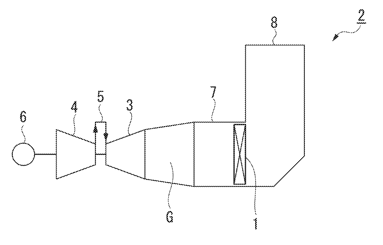
[0030]FIG. 1 is a schematic configuration view of a plant 2 which includes a gas turbine 3 (rotating machine) according to the first embodiment of the present invention.

[0031]As shown in FIG. 1, the plant 2 includes a compressor 4 which compresses air, a combustor 5 which combusts the air compressed by the compressor 4, and a gas turbine 3 which is operated by combustion gas generated by the combustor 5. Moreover, a generator 6 is connected to the compressor 4. Furthermore, exhaust gas G (fluid) generated by the gas turbine 3 passes through a silencer 1 according to the present embodiment provided in a duct 7 and is discharged from a funnel 8 which extends in a vertical direction.

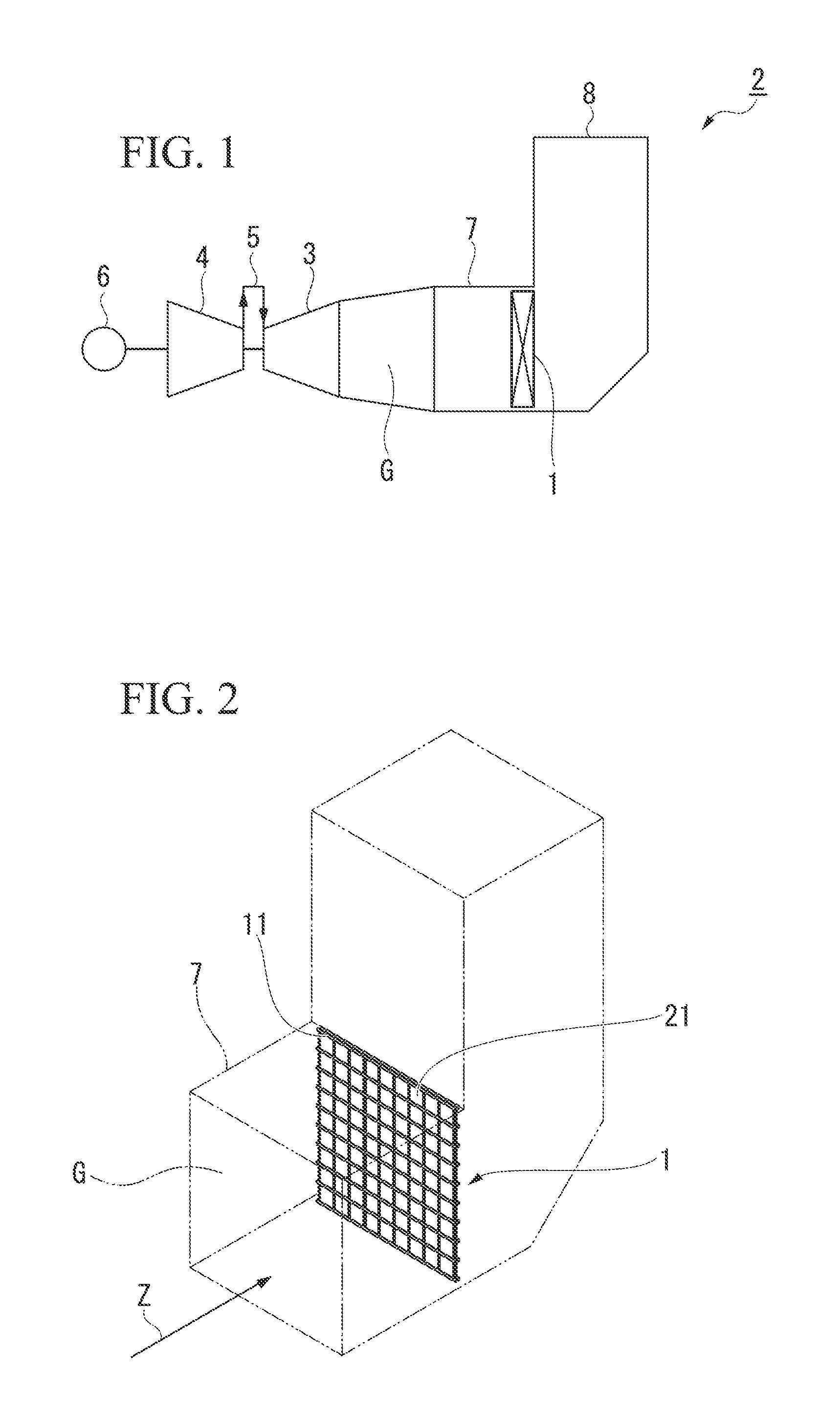
[0032]As shown in FIG. 2, the silencer 1 includes a frame member 11 which is provided to be perpendicular to a direction of a passage Z of the exhaust gas G in the duct 7 in...

second modification

[0042]Hereinafter, a silencer 201 according to a second embodiment of the present invention will be described referring to FIG. 5.

[0043]In this embodiment, the same reference numerals are attached to the members common to the members used in the above-described embodiment, and the descriptions are omitted.

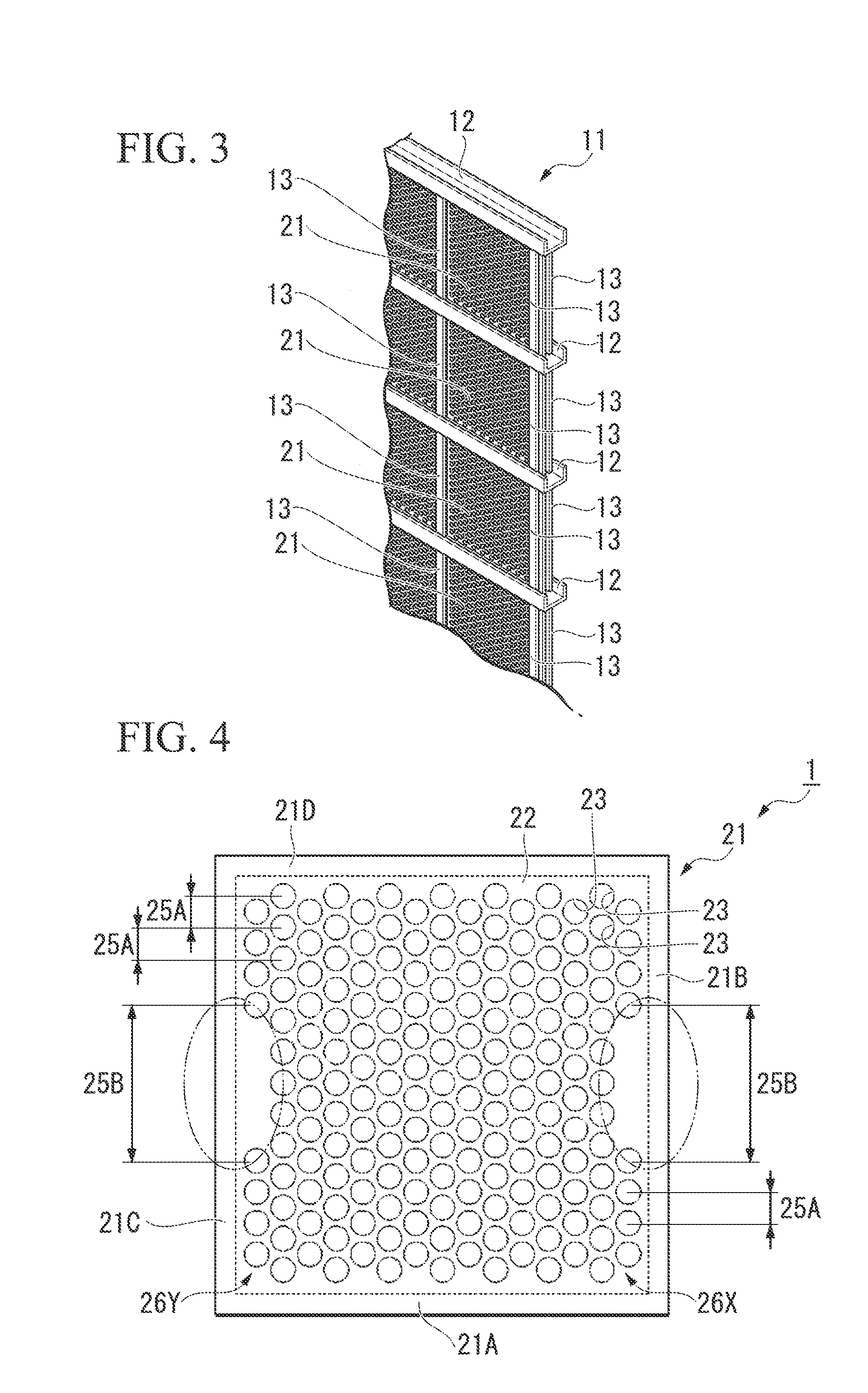
[0044]In the silencer 1 according to the first embodiment, the disposition intervals of the holes 23 in the approximately center portions and the end portions of the outer edge hole rows 26X and 26Y are different from each other, and thus, the disposition intervals of the holes 23 in the approximately center portions of the outer edge hole rows 26X and 26Y are set so as to be larger than the disposition intervals of the holes 23 of the rows inside the outer edge hole rows 26X and 26Y. On the other hand, in the silencer 201 according to the present embodiment, the disposition intervals of the holes 23 of outer edge hole rows 226X and 226Y are constant, and the disposition intervals ...

third embodiment

[0048]Hereinafter, a silencer 301 according to a third embodiment of the present invention will be described referring to FIG. 6.

[0049]In this embodiment, the same reference numerals are attached to the members common to the members used in the above-described embodiments, and the descriptions are omitted.

[0050]In the silencer 1 according to the first embodiment, the vertical direction in which the holes 23 are disposed is the same as the direction of the right side 21B (or left side 21C) of the plate member 22. On the other hand, in the silencer 301 according to the present embodiment, the direction in which the holes 23 are disposed is provided so as to be inclined from the directions of a right side 321B and a left side 321C of a plate member 322.

[0051]That is, in the present embodiment, the direction (P direction shown in FIG. 6) in which the holes 23 are disposed with a predetermined interval is provided so as to be inclined at 15° from the direction (Q direction shown in FIG. ...


PUM


Abstract

In a silencer, holes are disposed in one row with intervals to each other along one direction, holes forming the one row are disposed in a plurality of rows in a direction perpendicular to the one direction, and positions of the holes in adjacent rows are shifted in the one direction and disposed in a zigzag pattern. A disposition interval of the holes of an outer edge hole row forming one row in at least two sides opposite to each other in the silencing porous plate is set to be larger than a disposition interval of the holes of a row inside the outer edge hole row.

Description

TECHNICAL FIELD[0001]The present invention relates to a silencer and a rotating machine equipped therewith.[0002]Priority is claimed on Japanese Patent Application No. 2012-016761, filed Jan. 30, 2012, the content of which is incorporated herein by reference.BACKGROUND ART[0003]Generally, in a gas turbine, exhaust gas from an exhaust duct becomes a high temperature state of 600° C. or more and is led out at a flow rate of 30 m / second, and at this time, there is a problem in that noise occurs at an outlet of the gas turbine.[0004]Thus, in the related art, a technology is adopted in which a splitter silencer, in which a plurality of silencer panels having silencing effects are disposed along a passage of exhaust gas, is provided in a duct of a gas turbine, and thus, noise is prevented at the time of outflow of the exhaust gas (refer to Patent Document 1 below).[0005]Moreover, a technology regarding silencing is also known in which a silencer, which includes a frame assembled in a latt...

Claims


Application Information

Patent Timeline
IPC IPC(8): F02C7/24
CPCF02C7/24F01D25/30F24F13/24F02C7/045G10K11/162F05D2260/96F05D2250/183F05D2260/941F04D29/664
Inventor KATOU, EIGOAOTA, TOYOSEIMORITA, HIDEYUKI
Owner MITSUBISHI POWER LTD
Why Eureka
Try Eureka