
Retaining ring installation tool

a technology for installing tools and retaining rings, which is applied in the direction of metal-working equipment, metal-working equipment, manufacturing tools, etc., can solve the problems of not being able to use for the installation of rings that require a large amount of insertion, complicated and expensive, and unduly complicating the use of tools, etc., to achieve the effect of convenient use and flexibility

Active Publication Date: 2006-02-07
SMALLEY STEEL RING CO
View PDF23 Cites 34 Cited by
  • Summary
  • Abstract
  • Description
  • Claims
  • Application Information

AI Technical Summary

Benefits of technology

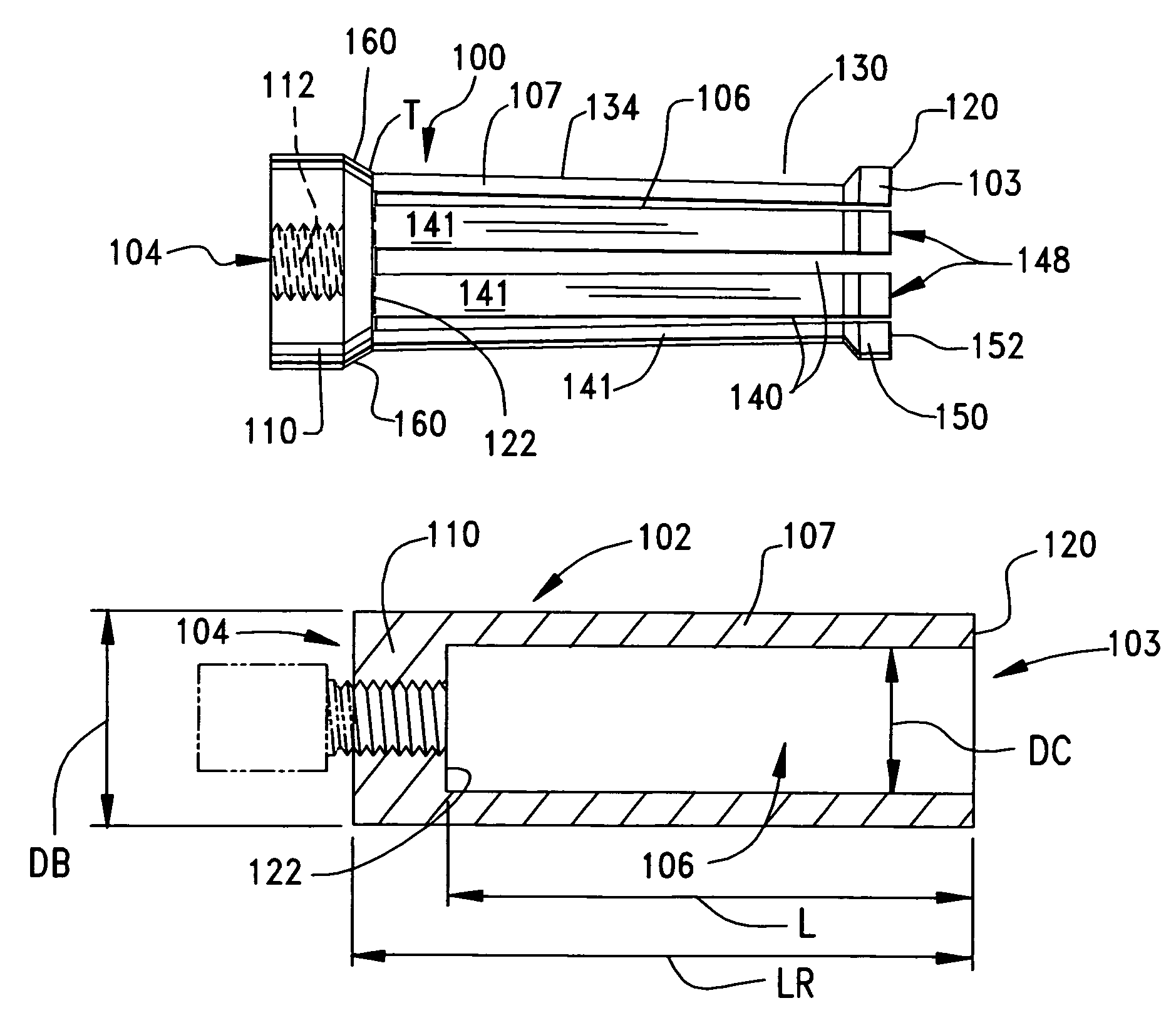
[0008]Accordingly, it is a general object of the present invention to provide a retaining ring installation tool that is used for the manual installation of metal retaining rings and which is formed from a single piece of metal and which possesses the necessary flexibility and strength to engage and install retaining rings.
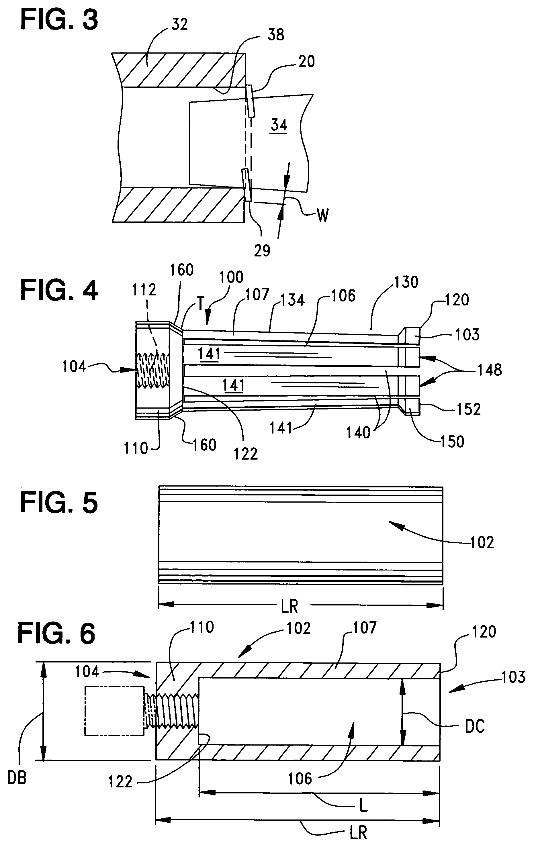
[0013]Still another object of the present invention is to provide a manual installation tool for retaining rings that utilizes a plurality of deflectable, slotted spring fingers that deflect inwardly or outwardly during installation and which have the same wall thickness to equalize the installation force encountered with use of the tool, the free ends of the spring fingers having enlarged end portions that have ring-contacting surfaces arranged thereon which extend generally perpendicularly to the longitudinal axis of the tool, the enlarged end portions having a height that exceeds the width of the retaining ring which the tool is used to install, thereby ensuring complete contact between the tool and the retaining ring.
[0015]Yet still another object of the present invention is to provide a retaining ring installation tool having a cylindrical hollow body, the body having a solid base and a plurality of distinct elongated spring arms that extend longitudinally from the base, the spring arms terminating in enlarged free ends that maintain contact with the retaining ring and the shaft or bore during installation, the spring arms being cooperatively defined by an internal cavity of the body that terminates at a location rearwardly of the location at which the spring arms extend from the base so as to reduce stress concentrations in the tool where the spring arms extend from the base.
[0019]The constant wall thickness extends along the body of the tool and assists in ensuring that a uniform application force is applied to the ring by the tool during installation. It also assists in providing the optimum installation force for manual use of the tool. In order to assure complete contact with the ring, the free ends of the spring fingers are increased in size to a diameter that is greater than the outer diameter of the body of the tool and which is slightly larger than the outer diameter of the rings which are used with the tool. These enlarged ends maintain contact with both the retaining ring and either the inner diameter of a bore or the outer diameter of a shaft during all steps of installation of the ring. Due to the forces encountered by the tool during use, the internal cavity terminates rearwardly of the point at which the spring fingers extend from the body. This ensures that there is an adequate amount of body material concentrated at the junction of the spring fingers to the body in order to reduce or eliminate stress concentrations at the junction.
[0020]In another embodiment of the invention, the free ends of the spring fingers are not enlarged, but are common with the outer diameter of the body of the tool so that the spring fingers have a constant wall thickness for their entire length. The thickness of the fingers are based on the diameter of the shafts for which the tool is used in order not to be adversely affected by the axial force encountered by an installer using the tool. Preferably, the tool is made from a metal having an ultimate tensile strength of 150,000 psi (pounds / square inch) or greater having a “memory”, which permits its spring fingers to expand outwardly or contract inwardly during use and returning to their original installation positions without any permanent deflection occurring in the spring fingers.
[0021]The installation tool is formed from a single piece of metal so as to maintain the simplicity of its design and to keep its cost of manufacture low. The unitary structure of the tool permits the insertion spring fingers to be made in a uniform thickness so to ensure that each such spring finger encounters approximately the same installation force during use. The insertion spring fingers may also be more easily bent into a smaller diameter so they initially may engage a tapered installation plug and extend therealong into reliable contact with the retaining ring. In instances where the installation tool is used to insert a retaining ring into a bore, the insertion spring fingers may be bent outwardly into a larger diameter so that the spring fingers, especially the engagement ends thereof may engage a tapered sleeve and extend therealong into reliable contact with the retaining ring.

Problems solved by technology

This requires the use of a double-acting piston, which is complicated and expensive.
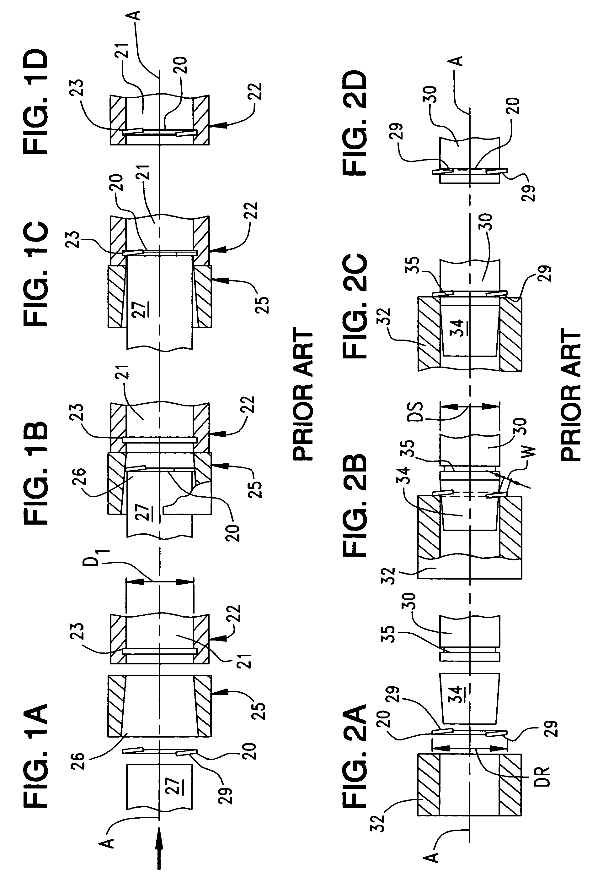
Because the insertion end must be inserted into a bore of a diameter smaller than that of the ring in order to seat the ring, it must be made of a material with a certain amount of deforming “give”, such as plastic or hard rubber, and will not be able to be used for the installation of rings that require a large amount of insertion force.
Such a tool further requires the use of a separate sleeve liner that unduly complicates the use of the tool.
All of these prior art devices are complicated assemblies formed from a plurality of pieces and have a structure where the force required to apply the ring to a shaft or a bore is great.

Method used


Image

  • Retaining ring installation tool
  • Retaining ring installation tool
  • Retaining ring installation tool

Examples


Embodiment Construction

[0036]As mentioned above, retaining rings are used to retain work elements on shafts or in bores. Retaining rings may be formed from square edge, flat wire stock that is edge wound around a form or mandrel, to obtain a specific diameter or they may be stamped from sheet or strip metal in the form of a circlip. Spiral retaining rings are usually formed into a single turn or into multiple turns of flat wire. For a single turn retaining ring, a gap exists between the free ends of the flat wire, and the total circumferential extent of the flat wire extent from which the ring is made does not exceed about 360 degrees. In a two-turn ring, the flat wire stock is wound around a mandrel twice so that it has a circumferential extent that equals or is slightly less than two winds of 360 degrees each.

[0037]Multiple-turn retaining rings may be assembled onto or into their supporting components in two manners. In manual assembly, one end of the flat wire is first separated and then inserted into ...


PUM

PropertyMeasurementUnit
ultimate tensile strengthaaaaaaaaaa
diametersaaaaaaaaaa
diametersaaaaaaaaaa

Abstract

A retaining ring installation tool for use in installing retaining rings onto shafts and into bores is formed from a single piece of metal to define a cylindrical, elongated body. A hollow cavity is formed in one end of the body and the wall of the body that defines the cavity is slotted to form a plurality of individual, flexible spring contact arms or fingers which extend forwardly from a rear body portion and which collectively define an insertion end of the tool. The ends of the fingers are enlarged to ensure contact occurs between the tool and the retaining ring during the installation of the ring onto a shaft or into a bore. The contact arms are bent either radially inwardly or outwardly so that they will contact the retaining ring at all times during installation of the ring.

Description

BACKGROUND OF THE INVENTION[0001]The present invention relates generally to metal retaining rings, and more specifically to tools that are used to manually install retaining rings on shafts or in bores.[0002]Retaining rings are widely used in many fields to retain working elements on either shafts or within cylinder bores. Retaining rings are used on cylindrical shafts to create a removeable shoulder that retains a plurality of working elements assembled thereon. Such retaining rings may be seated in a groove formed in the shaft, or they may grip the shaft in locations adjacent the working elements. Retaining rings may also be used to create a removeable shoulder within a bore that retains a plurality of working elements in place within the bore. In such instances, the retaining rings may be either seated in an inner, annular groove within the bore, or they may grip the bore adjacent the working elements.[0003]Retaining rings are commonly applied to shafts or in bores by the use of ...

Claims


Application Information

Patent Timeline
Patent Type & Authority Patents(United States)
IPC IPC(8): B23P19/04B25B27/00B25B27/20
CPCB25B27/0028B25B27/20Y10T29/53843Y10T29/5363
Inventor GREENHILL, MICHAEL
Owner SMALLEY STEEL RING CO
Learn More