Printed circuit board

Inactive Publication Date: 2005-05-31
TYCO ELECTRONICS BELGIUM EC
View PDF13 Cites 37 Cited by
  • Summary
  • Abstract
  • Description
  • Claims
  • Application Information

AI Technical Summary

Benefits of technology

[0006]It is therefore an object of the present invention to develop the printed circuit board in such a way that the surface contacts of the printed circuit board can b

Problems solved by technology

A known problem of these printed circuit boards is that the surface contacts of the printed circuit board can no longer be contacted reliably by the contact elements of the printed circuit board connector, if they are

Method used


Image

  • Printed circuit board
  • Printed circuit board
  • Printed circuit board

Examples


Embodiment Construction

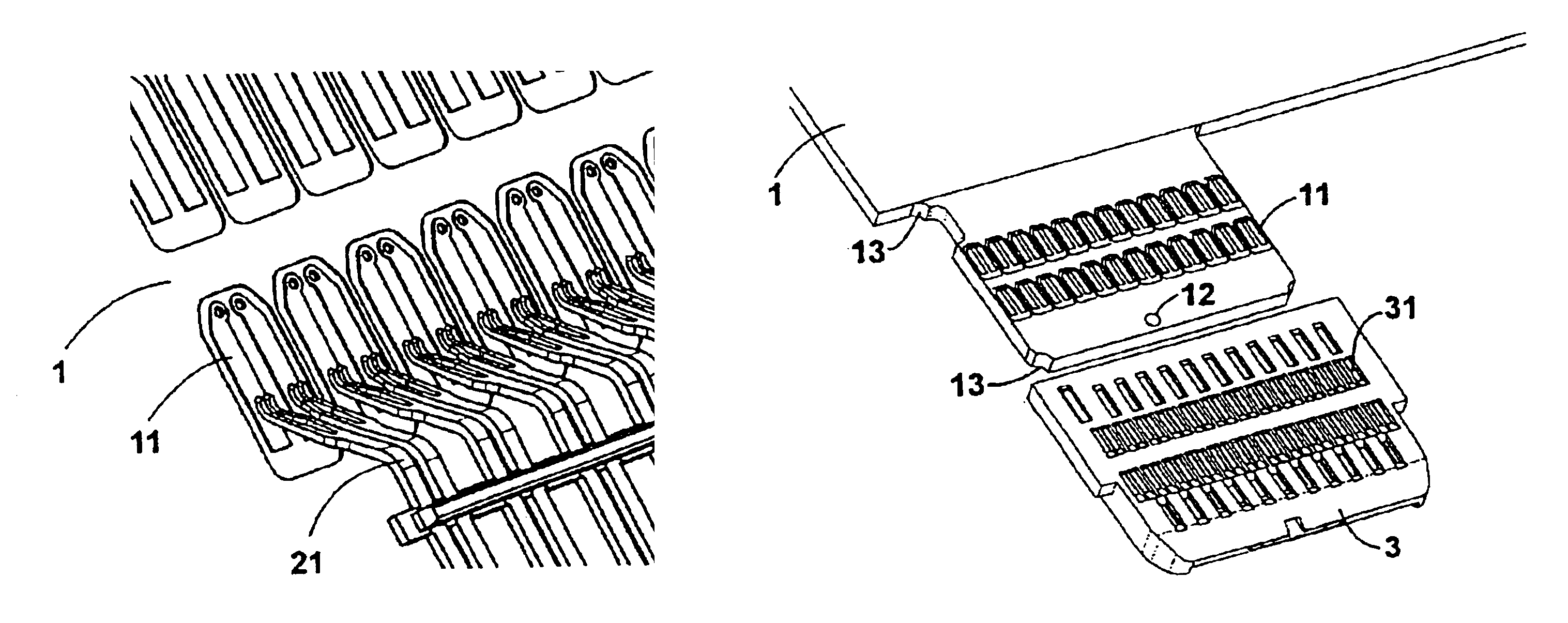
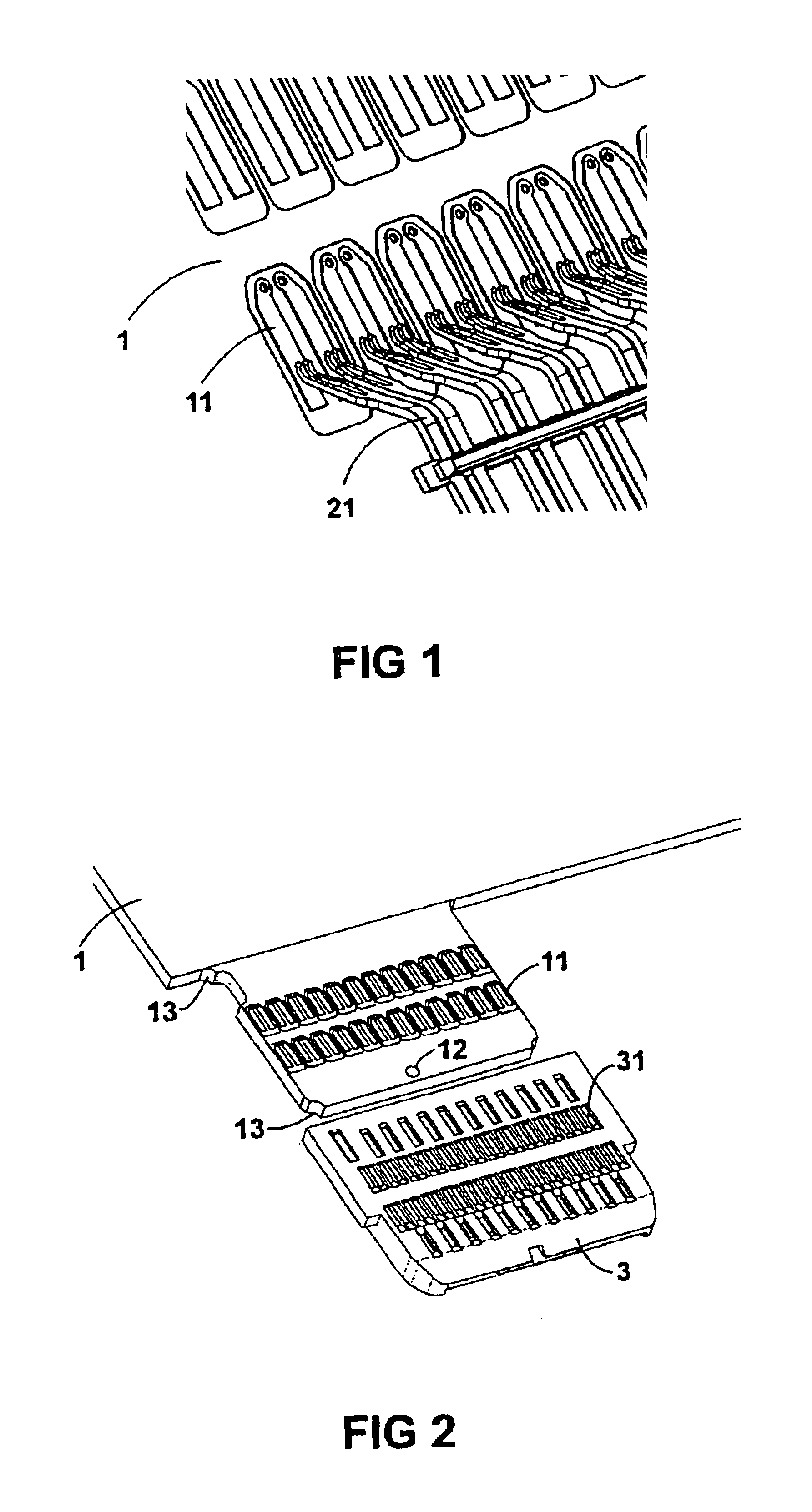
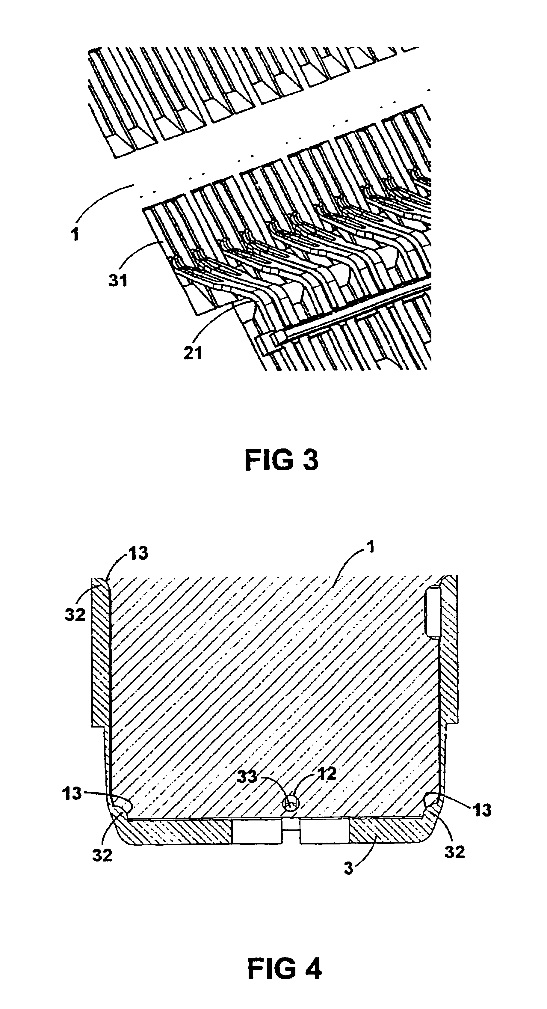
[0017]The printed circuit board described hereinafter is a printed circuit board which is designed to be connected via a printed circuit board connector to another printed circuit board or a different component of the system. The printed circuit board is connected to the printed circuit board connector via surface contacts that are provided on the printed circuit board and arranged in such a way that they can be contacted by contact elements of a printed circuit board connector.

[0018]The printed circuit board connector can (but need not) be mounted on another printed circuit board to which the currently considered printed circuit board is to be connected. In the example under consideration, this is a zero force printed circuit board connector, for example a connector according to DE 195 11 509 A1, DE 197 25 123 A1, DE 197 25 132 A1 and DE 197 25 138 A1. Zero force printed circuit board connectors of this type comprise two connector halves which are movable relative to one another an...


PUM


Abstract

A printed circuit board provided with an attachment which surrounds surface contacts of the printed circuit board that are to be contacted by a printed circuit board connector that covers the portion of the printed circuit board and edges of the printed circuit board around the surface contacts and includes recesses corresponding to the surface contacts assuring proper connection with contacts of a printed circuit board connector.

Description

BACKGROUND OF THE INVENTION[0001]1. Field of the Invention[0002]The present invention relates to a printed circuit board with surface contacts that can be contacted by contact elements of a printed circuit board connector.[0003]2. Description of Related Art[0004]Countless embodiments of printed circuit boards of this type have been known for many years. A known problem of these printed circuit boards is that the surface contacts of the printed circuit board can no longer be contacted reliably by the contact elements of the printed circuit board connector, if they are very small and / or are at very small distances from one another. It can happen that a contact element of the printed circuit board connector does not come into contact with the associated surface contact and / or that a contact element of the printed circuit board connector simultaneously comes into contact with a plurality of surface contacts, and / or that a plurality of contact elements of the printed circuit board connec...

Claims


Application Information

Patent Timeline
IPC IPC(8): H05K1/11H05K3/30H01R12/72
CPCH05K1/117H05K3/303H01R12/721H05K2201/09145Y10S439/951H05K2203/167H05K2203/0195Y02P70/50
Inventor LONGUEVILLE, JACQUESOCKET, TOMHOOLHORST, ALBERTBAERTSOEN, PETER
Owner TYCO ELECTRONICS BELGIUM EC
Why Eureka
Try Eureka