Continuously casting disconnecting device

A technology of cutting device and hydraulic device, applied in the field of continuous casting cutting device, can solve the problems of uncontrollable control method, hindering continuous casting cutting function, etc.

Inactive Publication Date: 2008-08-06
TOSHIBA MITSUBISHI-ELECTRIC IND SYST CORP
View PDF1 Cites 3 Cited by
  • Summary
  • Abstract
  • Description
  • Claims
  • Application Information

AI Technical Summary

Problems solved by technology

[0005] However, in the continuous casting cutting device driven by the above-mentioned hydraulic device, since the correlation between the moving speed control command of the hydraulic device for moving the hydraulic shear that cuts the slab and the moving speed of the hydraulic shear is nonlinear, Therefore, if the resulting speed deviation is large, there is a problem that it cannot be controlled by the control method of the above-mentioned conventional device, which hinders the normal operation of the cutting function of continuous casting.

Method used


Image

  • Continuously casting disconnecting device
  • Continuously casting disconnecting device
  • Continuously casting disconnecting device

Examples


Embodiment Construction

[0044] A preferred embodiment of the continuous casting cutting device according to the present invention will be described below with reference to the drawings.

[0045] Embodiment 1

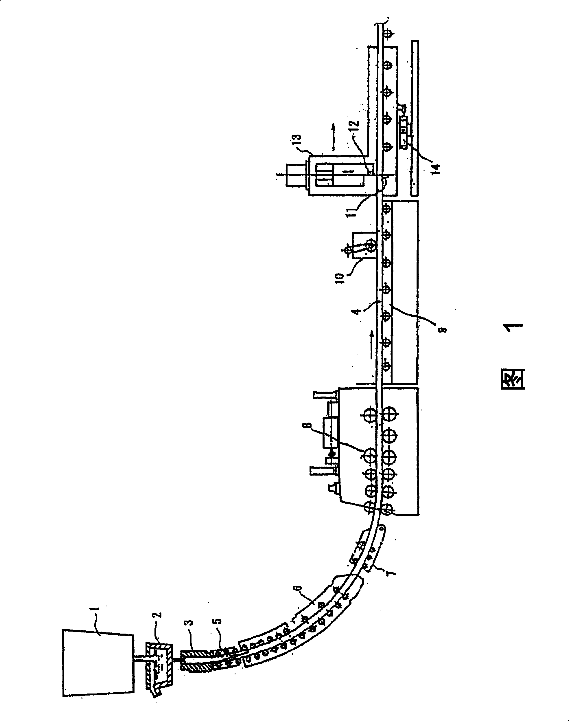
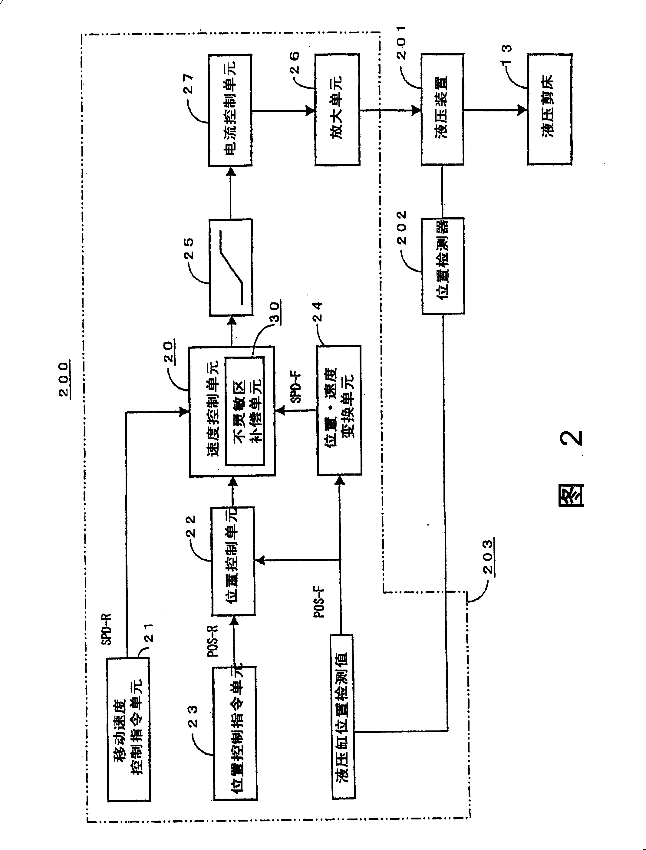
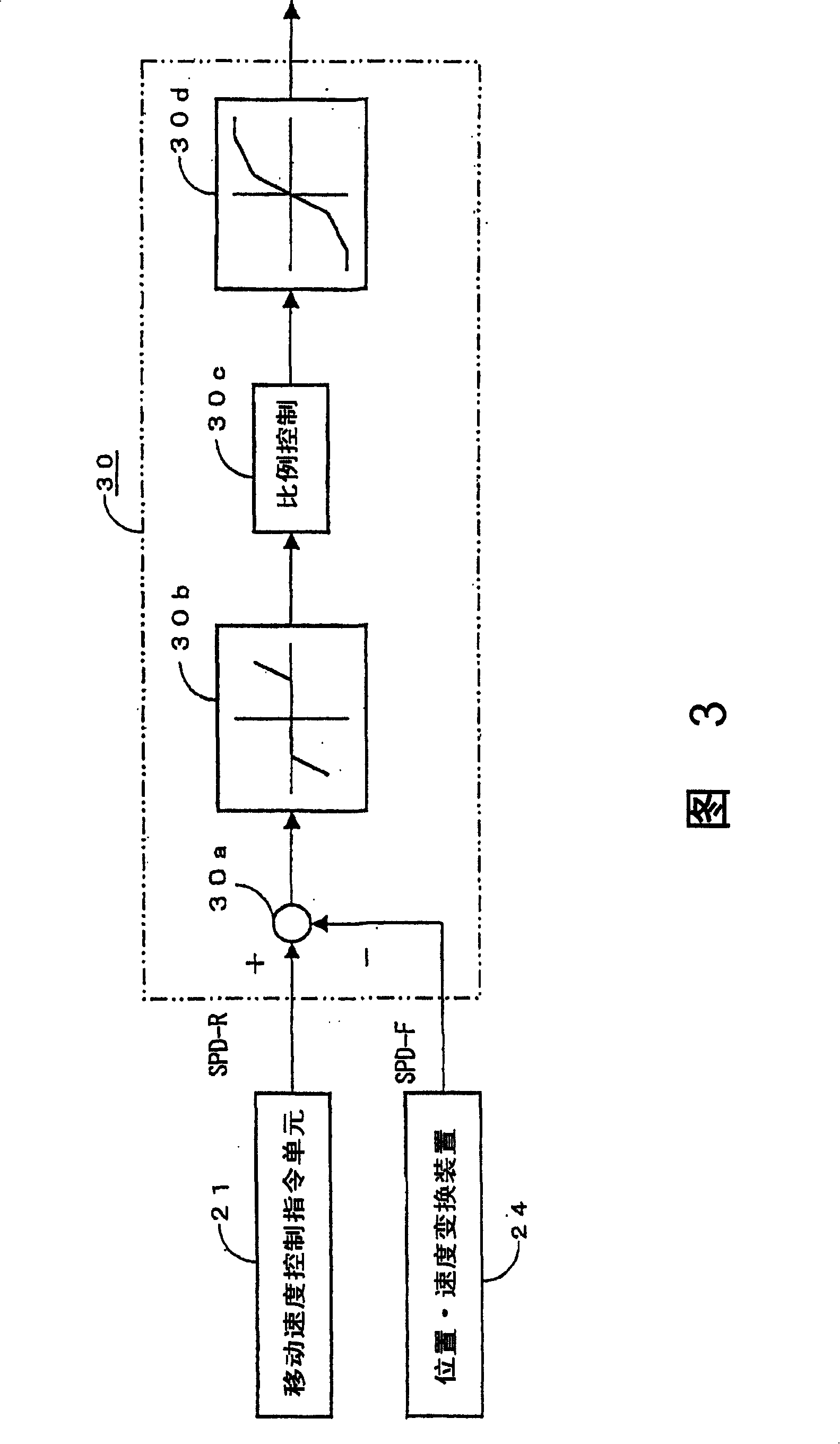
[0046] 1 to 3 are explanatory diagrams illustrating Embodiment 1 of the present invention, and FIG. 1 is an overall configuration diagram of a continuous casting apparatus employing a continuous casting and shearing apparatus related to the present invention. , FIG. 2 is a block diagram of the continuous casting cutting device, and FIG. 3 is a brief block diagram of the dead zone compensation unit included in the speed control unit of FIG. 2 .

[0047] First, an overall configuration diagram of a continuous casting machine employing a continuous casting cutting device according to the present invention will be described by citing the disclosure of the above-mentioned JP-A No. 2-295657. That is, in FIG. 1 , molten steel is placed in a ladle 1 , and molten steel is poured into each mold 3 from a...


PUM


Abstract

The invention provides a continuous casting and cutting device, which can keep the deviation value of the control instruction of the moving speed of the casting strip, that is, the moving speed of the hydraulic device and the moving speed of the hydraulic guillotine shear to the minimum. The control unit (200) of the hydraulic device is provided with a inactive area compensation unit (30) which controls the moving speed control instruction of the hydraulic guillotine shear (13) which is equal to the moving speed of the casting strip (4), and outputs the deviation with the moving speed testing value in the stated delay time. The inactive area compensation unit (30) generates the deviation between the moving speed control instruction SPD-R of the hydraulic guillotine shear (13) which is equal to the moving speed of the casting strip (4) and the moving speed SPD-F of the hydraulic guillotine shear (13) at the comparison part (30). After sending the deviation to the inactive area compensation part (30b), through the ratio control part (30c) which is used for ratio controlling, the compensation unit (30) then outputs to the retardation compensation part (30d) to retardation compensate the change of the output and keeps the un-matching value between the moving speed of the casting strip (4) and the moving speed of the hydraulic guillotine shear (13) to the minimum.

Description

technical field [0001] The present invention relates to a continuous casting cutting device, in particular to a hydraulic cylinder stretching and contracting according to the moving speed of the slab, so that a hydraulic shear directly connected to the hydraulic cylinder moves and cuts the slab, and then A continuous casting cut-off device that resets hydraulic shears. Background technique [0002] As such a conventional device, there is a method of synchronizing the moving speed of a hydraulic shear with the slab take-out speed (pinch roll speed), and cutting the slab continuously supplied from a pot storing molten steel. The following techniques are well known for moving cutting devices to a predetermined length. [0003] That is, a proportional electromagnetic flow control valve, a casting speed detector for detecting the speed of pinch rolls, and a speed control unit are provided in a hydraulic circuit of a shear moving hydraulic cylinder of a hydraulic shear for a cont...

Claims


Application Information

Patent Timeline
Patent Type & Authority Applications(China)
IPC IPC(8): B22D11/126
Inventor 大谷正司
Owner TOSHIBA MITSUBISHI-ELECTRIC IND SYST CORP
Why Eureka
Try Eureka