Support frame

A technology of support frame and support arm, applied in the field of support frame

Inactive Publication Date: 2010-09-29
TOPTRONICS +2
View PDF3 Cites 0 Cited by
  • Summary
  • Abstract
  • Description
  • Claims
  • Application Information

AI Technical Summary

Problems solved by technology

[0004]However, most of the traditional support structure, because the cantilever and the base adjust the height and the corresponding angle between the two, it often results in the The original spatial position angle of the fixed plate at the upper end of the cantilever changes. For example, the fixed plate usually has the problem of angular deflection facing upward or downward, which often causes the fixed objects (such as display screens) assembled on the fixed plate to be distorted. The viewing angle causes upward or downward deflection, and the display screen cannot be kept at the same angle position, causing consumers to need to adjust again and again, causing great inconvenience in use
[0005] It can be seen from this that the above-mentioned existing support frame obviously still has inconvenience and defects in structure and use, and needs to be further improved urgently
In order to solve the above-mentioned problems, the relevant manufacturers have tried their best to find a solution, but no suitable design has been developed for a long time, and the general products do not have a suitable structure to solve the above-mentioned problems. This is obviously related. The problem that the industry is eager to solve

Method used


Image

  • Support frame
  • Support frame
  • Support frame

Examples


Embodiment Construction

[0070] In order to further explain the technical means and effects of the present invention to achieve the intended purpose of the invention, the specific implementation, structure, characteristics and effects of the support frame proposed according to the present invention will be described in detail below in conjunction with the accompanying drawings and preferred embodiments. The description is as follows.

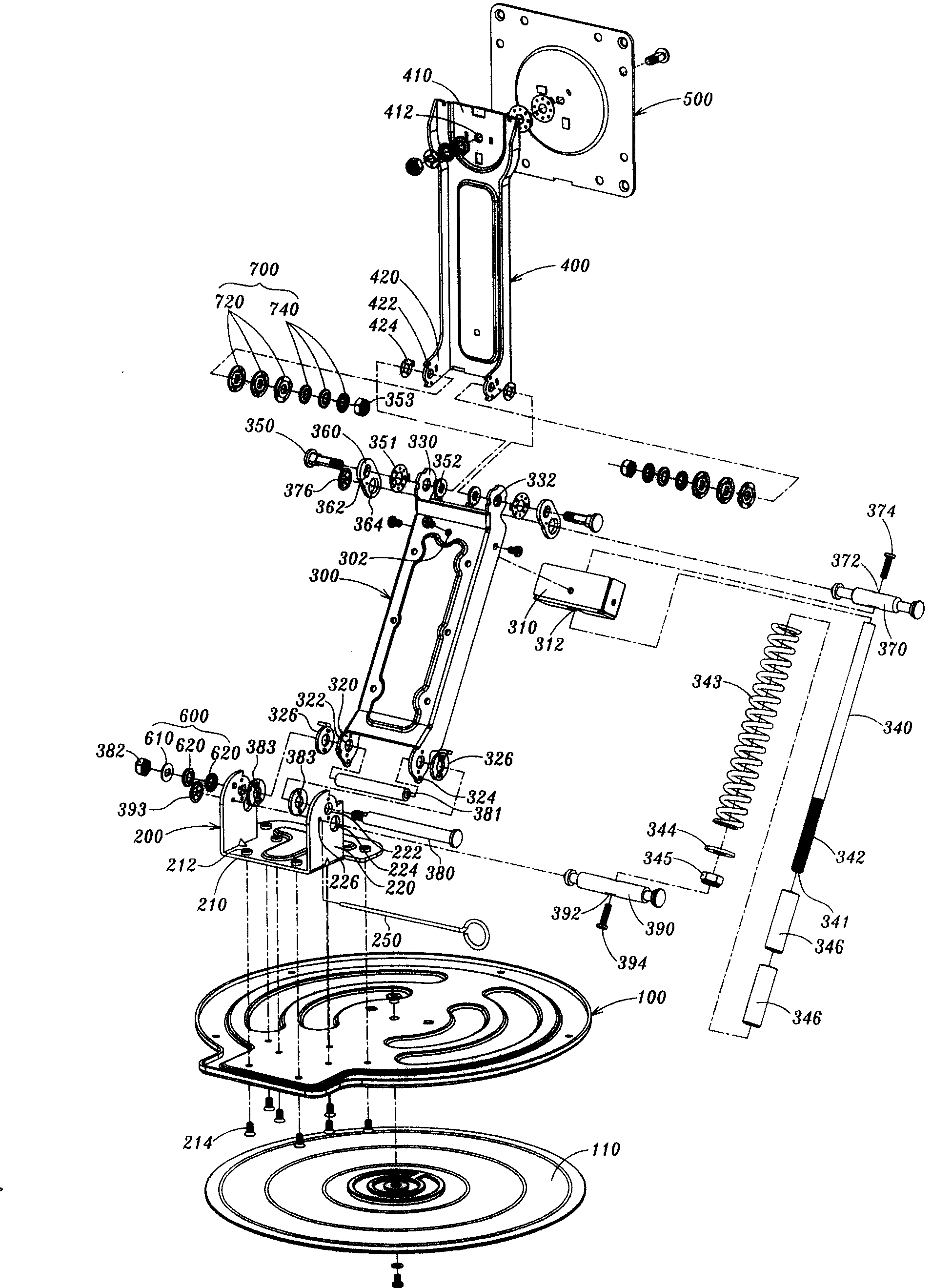
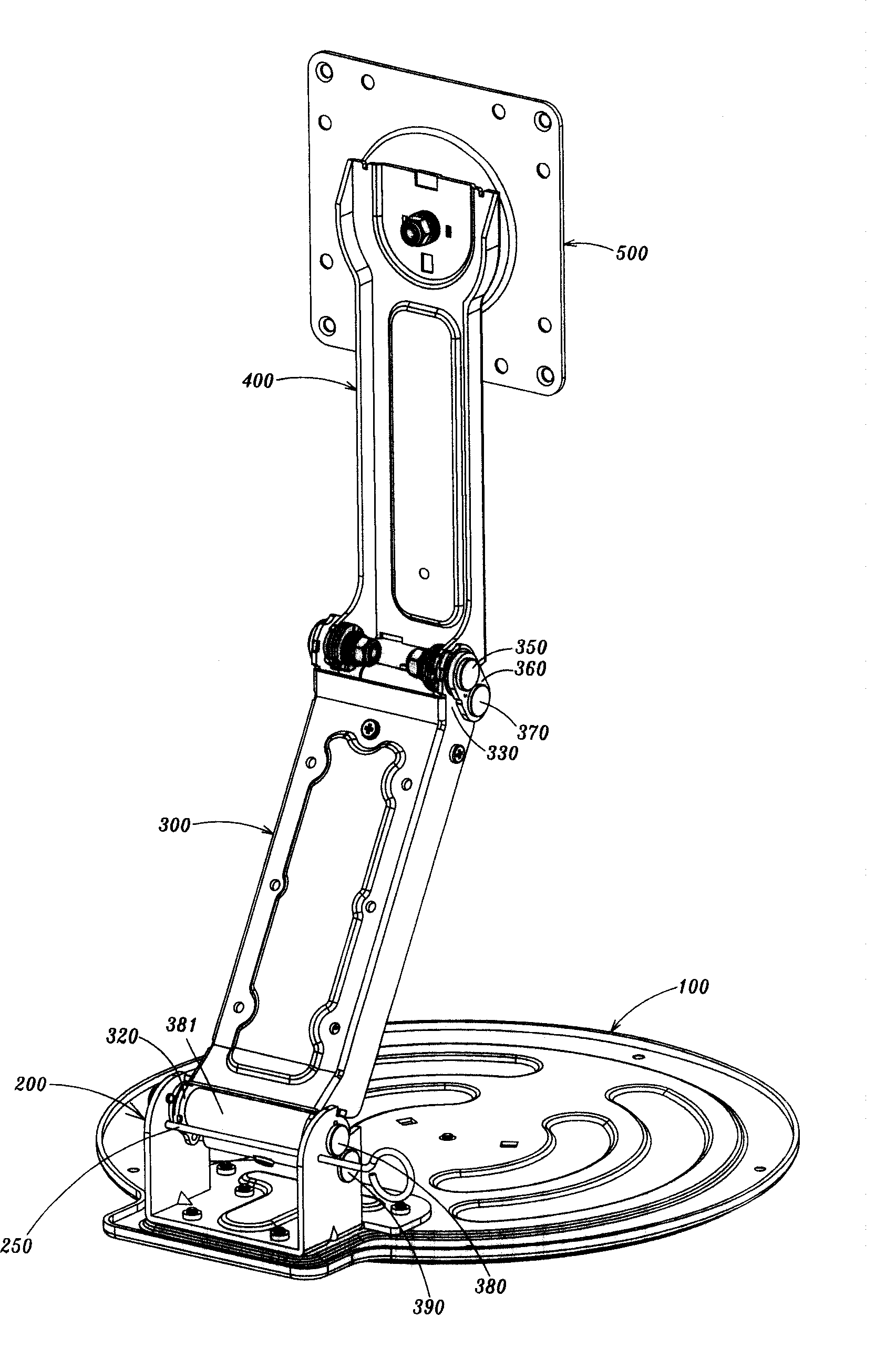
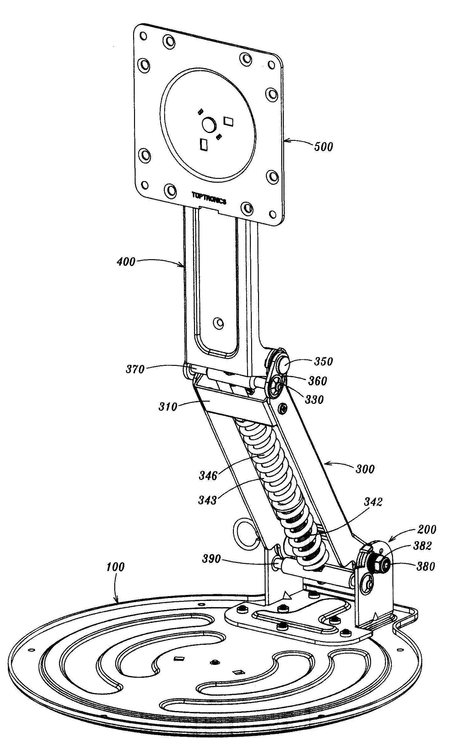
[0071] see figure 1 Shown is an exploded perspective view of a preferred embodiment of the support frame of the present invention. As shown in the figure, the supporting frame of the present invention mainly includes a base 100, a fixing base 200, a first supporting arm 300, a second supporting arm 400, and a fixing plate 500; wherein:

[0072] The base 100 mentioned above provides the fixing base 200 which can be assembled on its surface. exist figure 1 In the illustrated embodiment, the base 100 is shown as a flat plate, which can be placed flat on a work surface...


PUM


Abstract

The invention relates to a support frame, comprising a base, a permanent seat, a first sway brace, a second sway brace and a fixing plate. Effect of a four bar linkage which is shown as a parallelogram and made up via making use of the permanent seat, the first sway brace, an arranged connecting sheet and a knighthead comprises: when the first sway brace processes to turn and adjust angular position corresponding to the permanent seat, the second sway brace which is axially fixed on the top of the first sway brace can still keep an intrinsic angle of elevation with the first sway brace so as to make a fixity which is fixed on the fixing plate keep on the position of the intrinsic angle of elevation. Thereby, user can freely adjust the angle of the first sway brace corresponding to the permanent seat so as to adjust the position of the permanent seat up / down in the space. The invention has the advantages of that, the user can easily operate the fixity on the permanent seat, and when the user adjusts the angular position of the sway brace of the support frame, the fixity can still keep the intrinsic angle of elevation so that the invention is very suited for practicality.

Description

technical field [0001] The invention relates to a support frame, in particular to a support frame with a structure capable of adjusting any spatial angle position corresponding to a base. Background technique [0002] With the advent of the information age, modern people gradually need to spend more and more time in front of the computer screen in order to deal with work affairs and trivial chores in daily life. And because of the progress in the manufacture of LCD screens, more and more consumers are gradually adopting LCD screens as tools for displaying computer information or audio-visual multimedia home appliances. Due to the size and weight of the LCD screen is relatively light and thin, in addition to using the base attached to the product to place it on the table, consumers can also purchase a special support frame and fix the support frame on the table. Then the display screen group is set on the supporting frame for use. Since the supporting frame has the function...

Claims


Application Information

Patent Timeline
Patent Type & Authority Patents(China)
IPC IPC(8): G12B9/08G12B5/00F16M11/00G06F1/16G09F9/30
Inventor 郭淑玉朱国铭潘建文
Owner TOPTRONICS
Why Eureka
Try Eureka