Vehicle roof with at least two cover elements

A technology for covering parts and roofs, which is applied to road vehicles, passenger vehicles, vehicle parts, etc., to achieve the effect of increasing the amount of adjustment

Inactive Publication Date: 2008-09-03
WEBASTO AG
View PDF2 Cites 3 Cited by
  • Summary
  • Abstract
  • Description
  • Claims
  • Application Information

AI Technical Summary

Problems solved by technology

However, this has a disadvantageous effect when closing the front cover part, because a high driving force is required to counteract the spring force

Method used


Image

  • Vehicle roof with at least two cover elements
  • Vehicle roof with at least two cover elements
  • Vehicle roof with at least two cover elements

Examples


Embodiment Construction

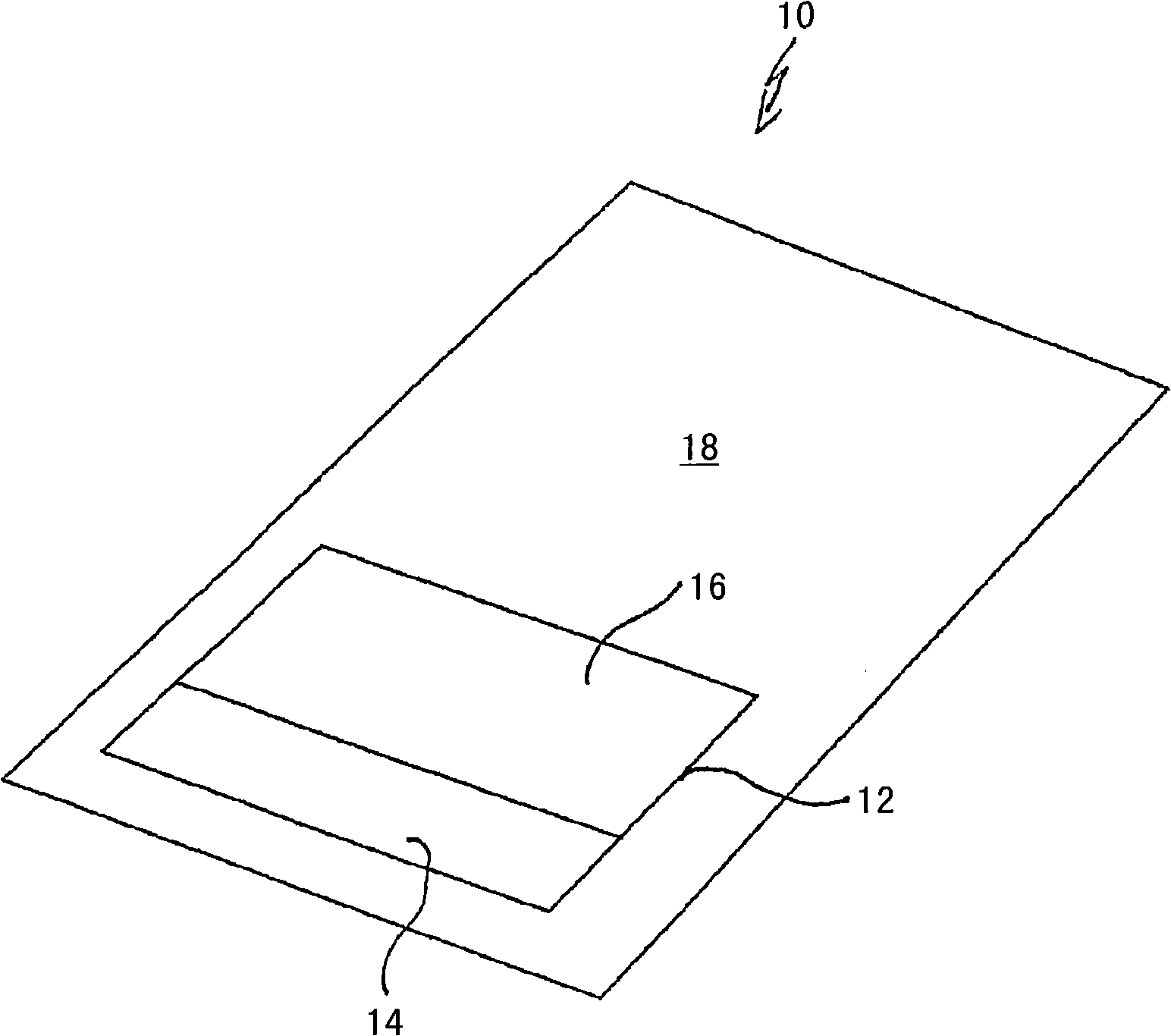
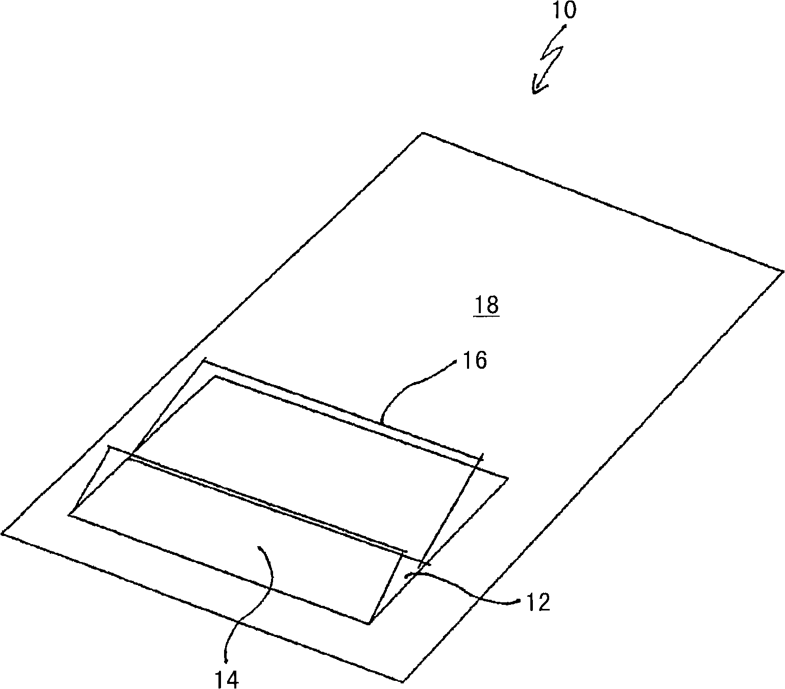
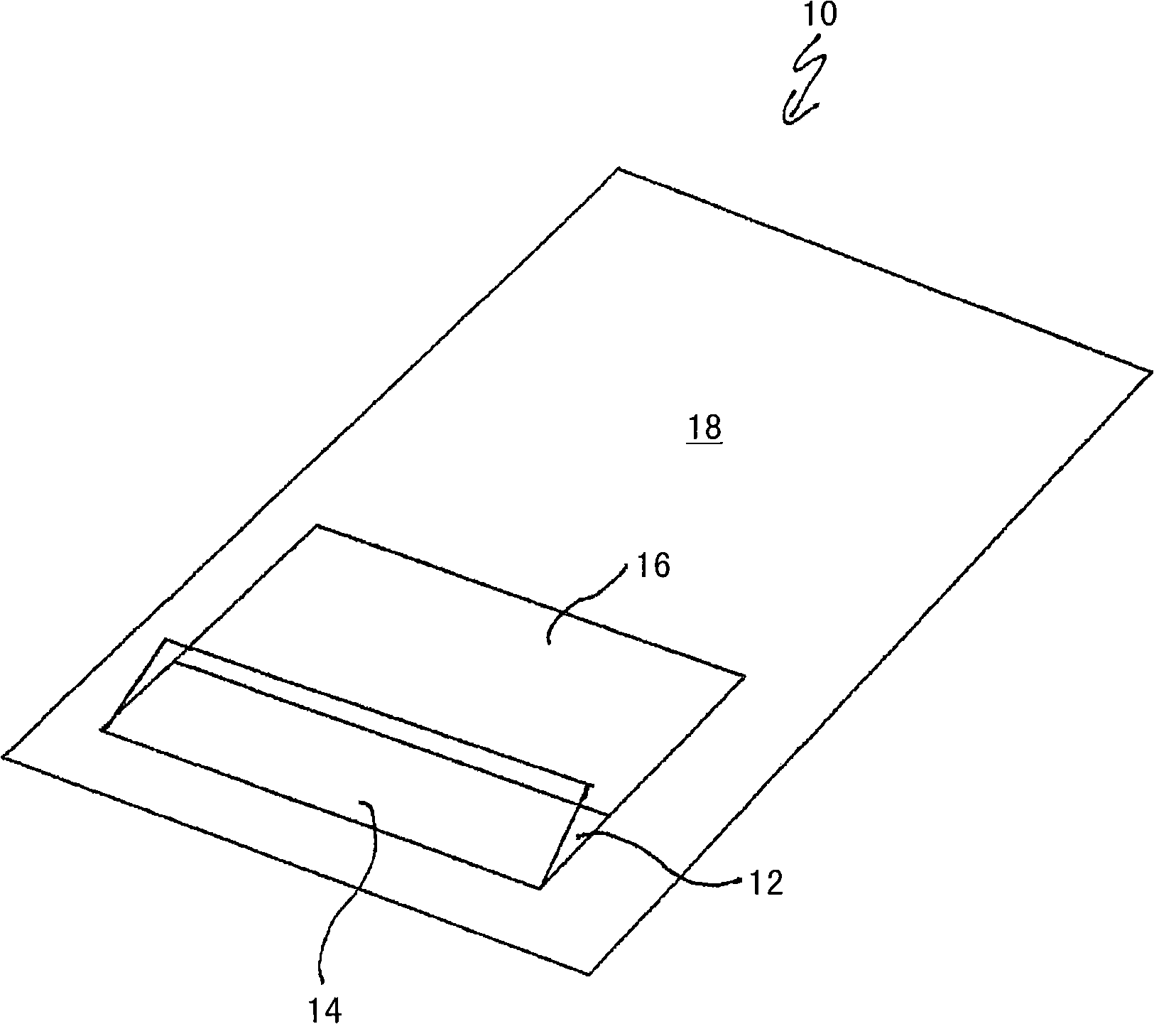
[0042] The drawing shows a vehicle roof 10 with a roof opening 12 which can be closed optionally by means of a cover part 14 located at the front in the direction of travel and a cover part 16 located at the rear in the direction of travel Or at least partially open. In this case, the two cover parts 14 and 16 can assume different positions. From figure 1 Starting from the closed position of the two cover parts 14 and 16 shown, such an arrangement of the two cover parts 14, 16 can be realized, wherein the two cover parts 14, 16 are opened and thus occupy a "ventilation position". ". exist figure 2 This vent position is shown in , which is also known as the dual vent position. Furthermore, an arrangement can be realized in which only the front cover part 14 is opened and thus in the ventilation position, while the rear cover part 16 is closed. exist image 3 This arrangement of the cover parts 14, 16 can be seen in FIG.

[0043] as especially in Figure 4 As can be see...


PUM


Abstract

The invention relates to a vehicle roof with two cover elements (14, 16), a front one of which can be deployed and a rear one of which serves as the sliding cover, can be lowered under the stationary vehicle roof and displaced. An embodiment of the invention relates to an actuating mechanism of a drive slide which interacts with a deployment lever in order to swivel the front cover element (14), said lever being hinged to a support of the front cover element (14). The deployment movement of the deployment lever is supported by a spring. According to another aspect of the invention, the actuating mechanism comprises a slide unit which comprises one control track each for the front cover element (14) and for the rear cover element (16).; The control tracks are configured in such a manner that the displacement of the slide unit in the direction of the vehicle roof, starting from a closed position of both cover elements (14, 16), first results in both cover elements (14, 16) being deployed, a continuous displacement of the slide unit in the same direction results in the rear cover element (16) being swung back and lowered and in the rear cover element (16) being retracted.

Description

technical field [0001] The invention relates to a vehicle roof according to claim 1 and the preamble to claim 8 having at least two cover parts which selectively close or at least partially open a roof opening. Background technique [0002] A vehicle roof of this type is known from EP 0 727 331 B1. In this vehicle roof, the front cover part is used as a windshield and the rear cover part is used as a slide cover. The front lid part can be opened with its rear edge over a fixed vehicle roof area. The rear cover part can be lowered below the fixed vehicle roof region and can be moved along guide rails arranged on both sides of the roof opening and fastened to the roof. In order to achieve different operating positions of the two cover parts, an actuating mechanism is provided which drives the two cover parts jointly. [0003] Furthermore, DE 35 22 781 A1 discloses a vehicle roof of the type mentioned in the introduction with a front cover part and a rear cover part, wherein...

Claims


Application Information

Patent Timeline
Patent Type & Authority Applications(China)
IPC IPC(8): B60J7/22B60J7/053
CPCB60J7/22B60J7/053B60J7/043B60J7/057B60Y2200/11
Inventor C·德容
Owner WEBASTO AG
Why Eureka
Try Eureka