Back light source device

A technology of backlight source and fluorescent layer, applied in optics, nonlinear optics, instruments, etc., can solve problems such as size increase

Inactive Publication Date: 2008-09-24
沈育浓
View PDF0 Cites 1 Cited by
  • Summary
  • Abstract
  • Description
  • Claims
  • Application Information

AI Technical Summary

Problems solved by technology

However, as the size of the screen becomes larger, the size of the backlight device, which is very important in the liquid crystal display device, will also increase accordingly. This is contrary to the reason why the liquid crystal display device has become the mainstream of the market.

Method used


Image

  • Back light source device
  • Back light source device
  • Back light source device

Examples


Embodiment Construction

[0012] In the following detailed description of preferred embodiments of the present invention, the same or similar elements are denoted by the same reference numerals, and their detailed descriptions will be omitted. In addition, in order to clearly reveal the features of the present invention, elements in the drawings are not drawn in actual scale.

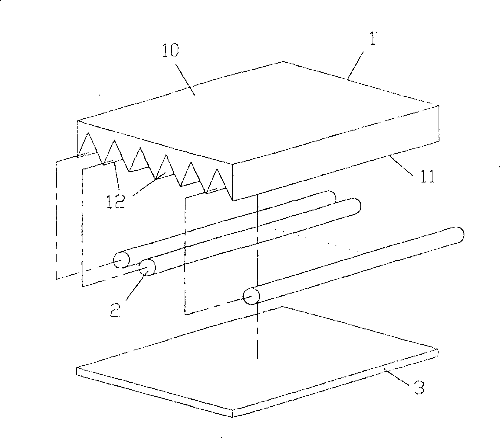
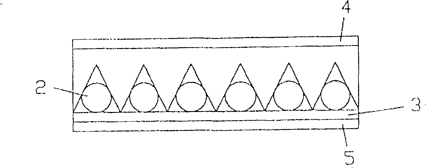
[0013] see Figures 1 to 4 As shown, the backlight device of the preferred embodiment of the present invention includes a first transparent plate 1 , several lamp tubes 2 , and a second transparent plate 3 .

[0014] The first transparent plate 1 has an upper surface 10 , a lower surface 11 opposite to the upper surface 10 , and several elongated grooves 12 formed on the lower surface 11 . It should be noted that, in this embodiment, the grooves 12 are V-shaped grooves, however, the grooves 12 are not limited to be V-shaped, and can be any suitable shape.

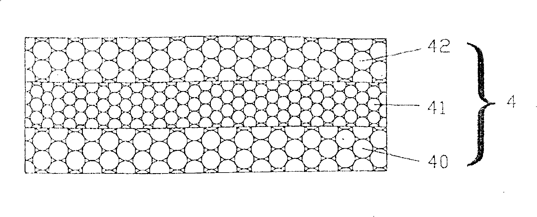
[0015] In this embodiment, a fluorescent layer 4 is formed on the uppe...


PUM


Abstract

A backlight source device comprises a first transparent plate which is provided with an upper surface, a lower surface opposite to the upper surface, a plurality of V-shaped grooves which are formed at the lower surface and extend along the lengthways direction of the first transparent plate, a plurality of lighting tubes arranged inside the corresponding grooves and a second transparent plate which is provided with a upper surface and the second surface opposite to the upper surface. The upper surface of the second transparent plate facing the lower surface of the transparent plate is connected with the first transparent plate.

Description

field of invention [0001] Generally speaking, the present invention relates to a backlight device for a display device, and specifically, the present invention relates to a backlight device for a display device that does not become larger due to an increase in screen size of the display device. technical background [0002] Liquid crystal display devices have become mainstream in the current market due to their advantages of being thin and light. Furthermore, there is a tendency for the screen size of the liquid crystal display device to become larger and larger. However, as the size of the screen increases, the size of the backlight device, which is very important in the liquid crystal display device, will also increase accordingly, which is contrary to the reason why the liquid crystal display device has become the mainstream of the market. Contents of the invention [0003] The purpose of the present invention is to provide a backlight device, which can maintain the ad...

Claims


Application Information

Patent Timeline
Patent Type & Authority Applications(China)
IPC IPC(8): G02F1/13357G02F1/1335
Inventor 沈育浓
Owner 沈育浓
Why Eureka
Try Eureka