Electrical connector with spike protection and method for production of a spike protection for electrical connectors

A technology of electrical connectors and connectors, which is applied to the parts, connections, circuits, etc. of the connection device, and can solve the problems of shrinkage hose damage and non-replacement

Inactive Publication Date: 2008-10-01
SIEMENS AG
View PDF3 Cites 0 Cited by
  • Summary
  • Abstract
  • Description
  • Claims
  • Application Information

AI Technical Summary

Problems solved by technology

Shrink tubes can also be used to cover mated mating pairs, but this has the disadvantage that the shrink tube has to be destroyed when the plug connection is disconnected and is usually not replaceable when used in an MRI system

Method used


Image

  • Electrical connector with spike protection and method for production of a spike protection for electrical connectors
  • Electrical connector with spike protection and method for production of a spike protection for electrical connectors
  • Electrical connector with spike protection and method for production of a spike protection for electrical connectors

Examples


Embodiment Construction

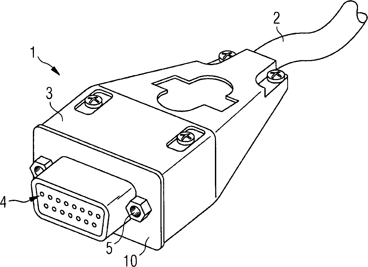
[0027] figure 1 Represents an electrical connector 1 and a cable 2 fixed thereon. The housing 3 of the connector 1 is entirely made of metal. Located on the end side of the connector 1 is a plug-in face 4 which, in the example shown, is a matrix-shaped contact socket. On both sides of the receptacle part of the connector there are threaded holes into which screws provided on the mating plug can be inserted in order to secure the receptacle connection.

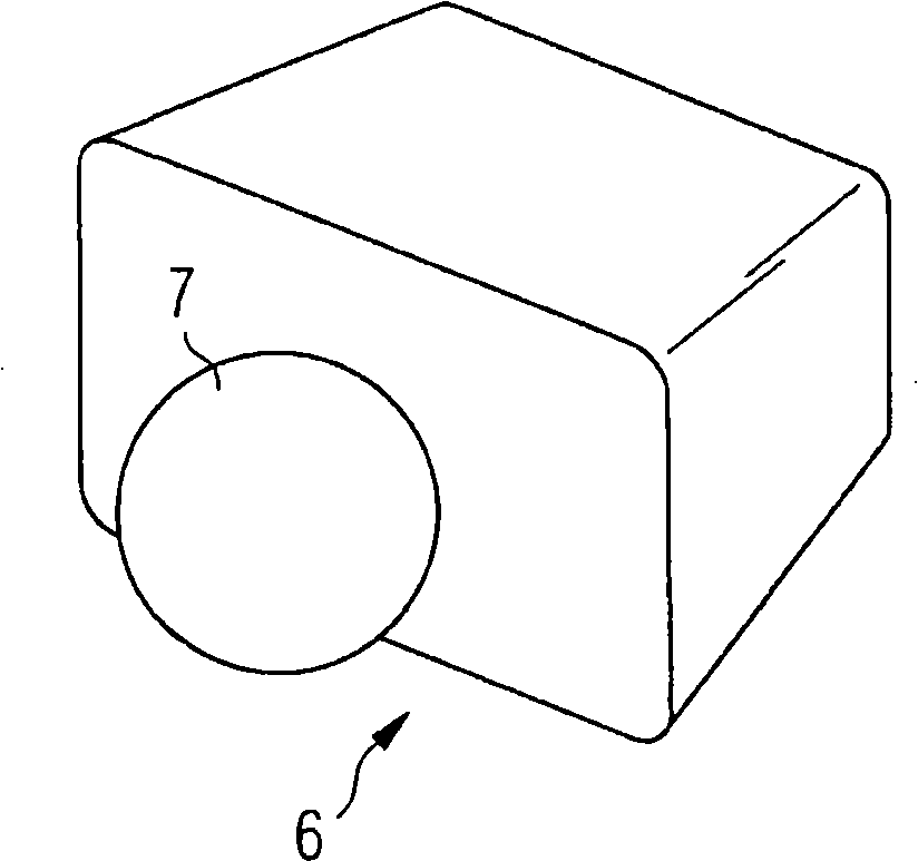
[0028] Figure 2A It shows a perspective view of the insert cover 6 obliquely downward. For easy handling of the plug-in cover, a knob is fixed on its rear side, which makes it easy to remove the plug-in cover from the connector 1 when the shrink hose is put on.

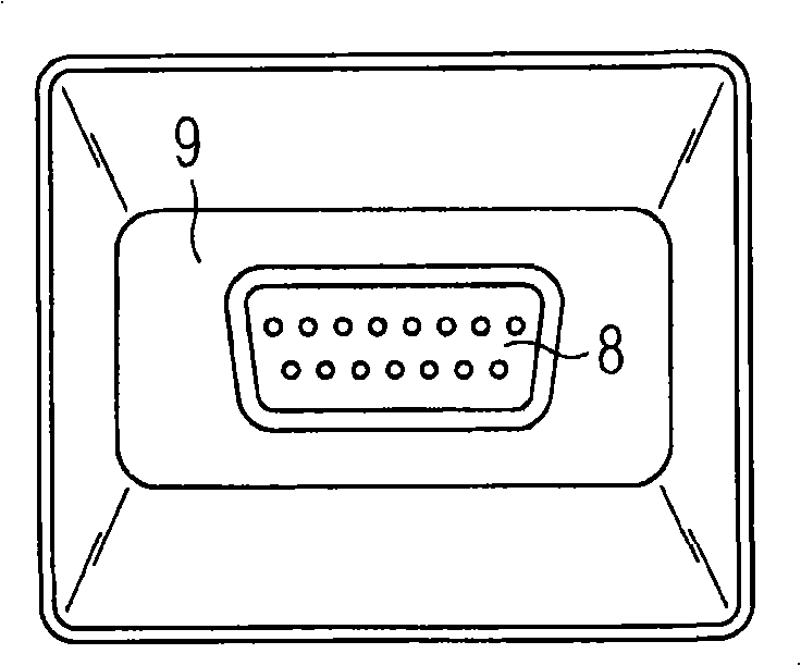
[0029] Figure 2B The front of the insert is shown. The figure shows a plug 8 complementary to the socket 4 with contact pins. However, the plug 8 does not have to be designed to have an effective contact function. Even if it only has a skirt, it is also suffi...


PUM


Abstract

The invention relates to an electric connector (1) with sharp wave protection. The connector is provided with a shell (3) at least partly metalized which has a cable side end and a plug side end. A protecting sleeve (11) made of insulating materials encases the whole connector (1) and forms an apron (12) crossing the shell and extending outwardly in the area of a splicing surface (4) of the connector (1) in the splicing direction.

Description

technical field [0001] The present invention relates to an electrical connector with spike protection and a method of providing spike protection to an electrical connector having an at least partially metallized housing. Background technique [0002] Many electrical devices, as well as imaging medical devices, such as magnetic resonance devices or medical computed tomography devices, have multiple electronic components that are interconnected by conductive cables. Most cables are electrically shielded cables, such as coaxial cables, which are used to prevent the signals transmitted through the conductors from being adulterated by electromagnetic interference (EMI). The electrical plug connectors usually have a metallized housing at the end of these cables, which is electrically connected to the shielding shell of the cable, so that no gaps are produced in the shielding shell. Metallic or metallized connector housings must not come into contact with metallic objects, since s...

Claims


Application Information

Patent Timeline
Patent Type & Authority Applications(China)
IPC IPC(8): H01R13/52H01R13/46
CPCH01R13/516
Inventor 赫尔穆特·比特纳
Owner SIEMENS AG
Why Eureka
Try Eureka