
Indicator apparatus

A technology of indicating devices and indicators, applied in the direction of measuring devices, control devices, indication of measured values, etc.

Inactive Publication Date: 2008-10-15
CONTINENTAL AUTOMOTIVE GMBH
View PDF0 Cites 6 Cited by
  • Summary
  • Abstract
  • Description
  • Claims
  • Application Information

AI Technical Summary

Problems solved by technology

However, the manufacture of these stops requires the highest manufacturing precision in the case of adjusting the geometry of the fragile ring indicator, resulting in significant costs

Method used


Image

  • Indicator apparatus
  • Indicator apparatus

Examples


Embodiment Construction

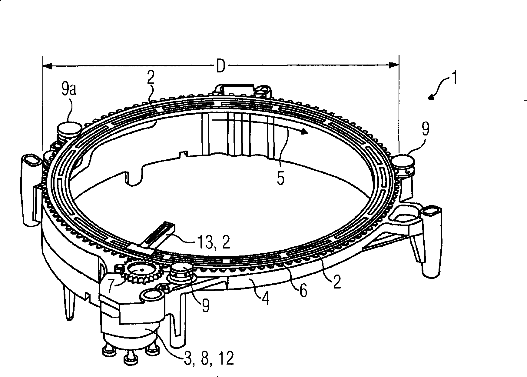
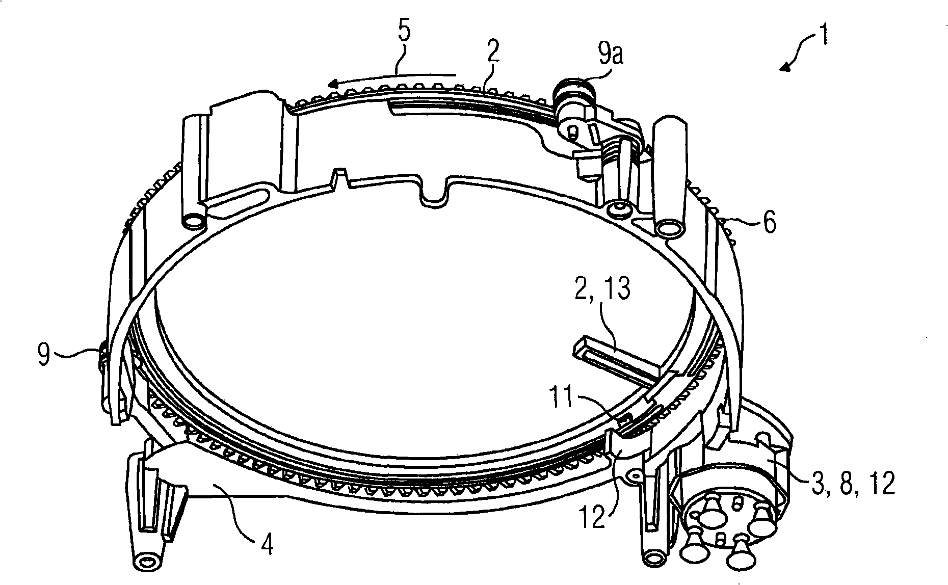
[0022] exist figure 1 and figure 2 shows an indicating device 1 according to the invention, respectively, wherein the indicating dial is omitted. The main components shown are the ring indicator 2 , the drive unit 3 and the support 4 . The ring indicator is provided on the outer diameter with a toothing 6 extending in the circumferential direction 5 . The toothing 6 is connected to a driven gear 7 of a drive unit 3 with a stepping motor responsible for moving the ring indicator 2 in or against the circumferential direction 5 . The annular indicator 2 is supported on the support 4 by means of three-part radial bearings 9, 9a, which each have a pulley with a U-shaped end tooth profile facing the basic part, annular The meshing outer circumference of the indicator 2 is guided in the face tooth profile. The radial bearing 9a, indicated at 9a, is designed elastically so that it can be elastically adapted radially outward. In the direct vicinity of the drive unit 3 , a stop 10...


PUM


Abstract

The invention relates to an indicator apparatus (1) having a ring pointer (2), which is mounted such that it can move in the circumferential direction (5), and having a drive unit (3), which drives the ring pointer (2) in the circumferential direction (5), wherein the ring pointer (2) interacts with a stop (10) in a manner limited in terms of its circumferential movement. Particularly in the case of synchronization, radial disengagement often occurs in conventional ring pointer arrangements, and the aim of the invention is to prevent this. In order to solve the problem, the invention proposes arranging the stop (10) directly next to the drive unit (3). The critical advantage of this is that the tangential force on the ring pointer (2) from the drive unit generates an only small disengagement moment on the ring pointer (2).

Description

technical field [0001] The present invention relates to an indicating device having: a ring-shaped indicator having a shape of a ring or a shape of a ring-shaped portion and arranged movably in a circumferential direction; a driving unit which drives the ring-shaped indicator in a circumferential direction The ring-shaped indicator has a limited area, and the indicating device has a stopper, and the stopper and the limited area jointly play a role in the limited circular movement of the ring-shaped indicator. Background technique [0002] In the era of increased information density in the motor vehicle cabin, especially for manufacturers of combination devices, great challenges arise, namely, to present high-density information, which is partly of safety-relevant significance, in a well-visible manner. Attention should also be paid to the relevant safety regulations, which should ensure a certain accuracy, for example, of the speed display under the condition of an appropria...

Claims


Application Information

Patent Timeline
Patent Type & Authority Applications(China)
IPC IPC(8): G01D13/22G01D11/16
CPCB60K37/02B60K2350/1064B60K2350/203G01D11/16G01D13/22Y10S116/06B60K2370/154B60K2370/33B60K2370/698
Inventor 阿克塞尔·弗尔斯特
Owner CONTINENTAL AUTOMOTIVE GMBH
Learn More