Siphon jet w.c.pan

A siphonic, toilet technology, applied in flushing equipment with water tanks, flushing toilets, urinals, etc., can solve problems such as consumption of flushing water, delay in starting, inability to meet water saving, etc., and achieve high flushing function and saving amount. Effect

Active Publication Date: 2008-11-05
TOTO LTD
View PDF2 Cites 4 Cited by
  • Summary
  • Abstract
  • Description
  • Claims
  • Application Information

AI Technical Summary

Problems solved by technology

If the flow rate of the flushing water decreases, the start of the siphon action will be delayed, and the flushing water will be consumed in vain accordingly, becoming a toilet that cannot meet the requirements of water saving.
[0015] Furthermore, in the jet siphon toilet of the above-mentioned Patent Document 2, the two streams of flushing water do not collide head-on in substantially the entire area at the time of merging as in Patent Document 1, and the merging part becomes a slightly larger space, so it is considered that the pressure loss is reduced. , but it is a toilet that cannot form a moderate pressure loss that can discharge the air in the spray water guide in a short time

Method used


Image

  • Siphon jet w.c.pan
  • Siphon jet w.c.pan
  • Siphon jet w.c.pan

Examples


Embodiment Construction

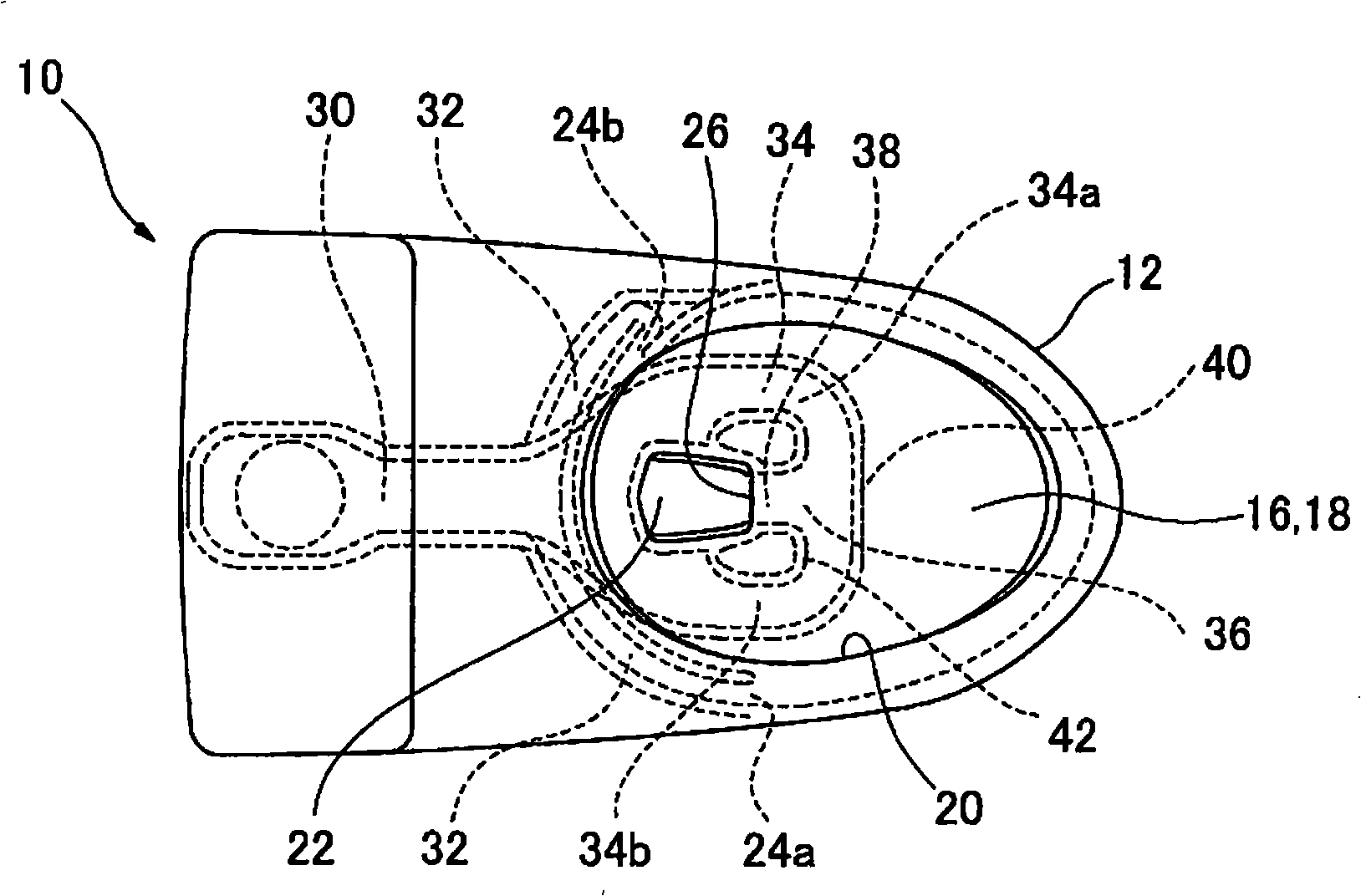
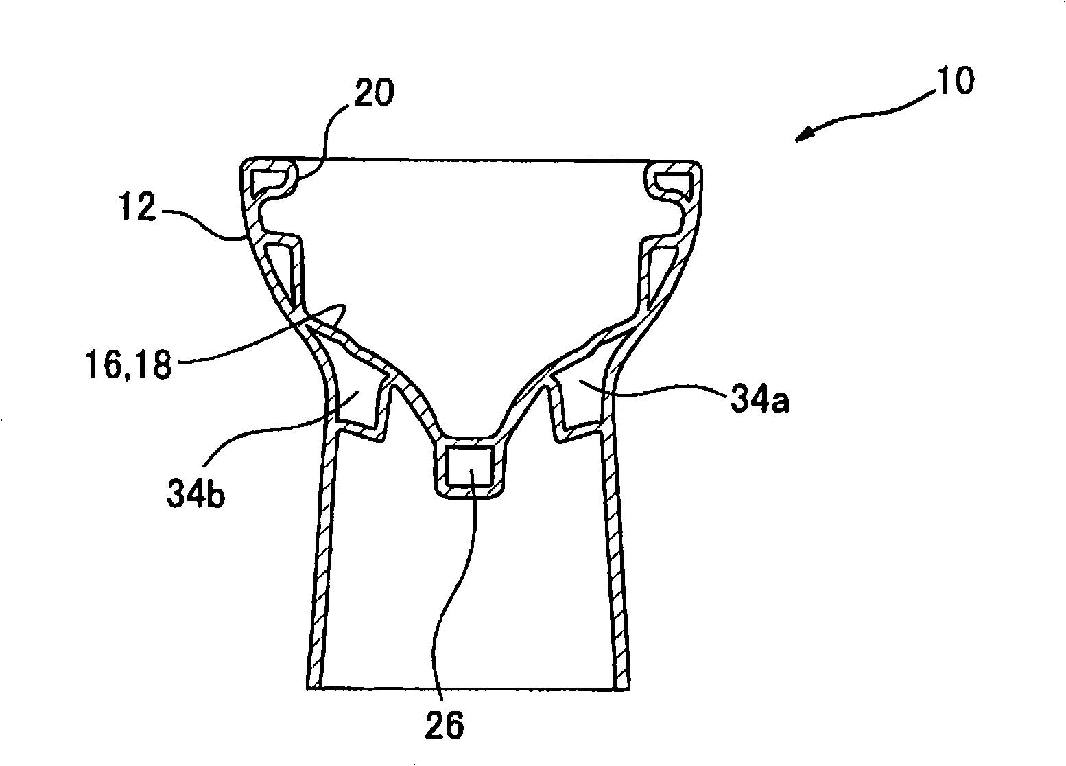
[0058] Next, a jet siphon toilet according to an embodiment of the present invention will be described with reference to the drawings. First, through Figure 1 to Figure 3 The basic structure of the jet siphon toilet according to the embodiment of the present invention will be described. figure 1 is a front sectional view showing a jet siphon toilet according to an embodiment of the present invention, figure 2 yes figure 1 top view of image 3 is along figure 1 Sectional view of line III-III.

[0059] Such as Figure 1 to Figure 3 As shown, the jet siphon toilet 10 of the present embodiment includes a toilet body 12 and a water storage tank 14 arranged at the rear upper portion of the toilet body 12 for storing flush water. The water storage tank 14 stores 2.5 liters of 6.5 liters of flushing water.

[0060] The toilet body 12 has a bowl portion 16 at the front portion, and a bowl-shaped dirt receiving surface 18 and an edge portion 20 as an upper edge portion are f...


PUM


Abstract

A siphon jet toilet for supplying flush water in a storage tank by using the head pressure thereof is disclosed. The siphon jet toilet has a toilet main unit furnished with a bowl portion, a rim water spout, a drain trap passage for expelling waste using siphon action, a jet water spout opening formed at a position opposite the inlet of the drain trap passage, a rim water channel for supplying flush water to the rim water spout opening, and a jet water channel for supplying flush water to the jet water channel. The jet water channel includes a plurality of branched water conduits, a merging portion for causing flush water from the plurality of branched water conduits to merge and swirl toward the jet water spout opening and a flow aligner for aligning the flow of flush water merged in the merging portion.; The merging portion including an outer wall portion formed in essentially a straight line so that flush waters in the outer region of the swirl collide head-on and an inner wall portion on which a bent portion is formed so that flush water in the inner region of the swirl flows smoothly toward the jet water spout opening.

Description

technical field [0001] The present invention relates to a jet siphon toilet, and more particularly to a jet siphon toilet for supplying flush water by utilizing the head pressure of flush water stored in a water storage tank. Background technique [0002] Conventionally, there is known a jet siphon toilet in which flush water is supplied to a jet outlet formed on a bowl (bowl) of the toilet body by utilizing the head pressure of flush water stored in a water storage tank, and the water is stored by drainage. The siphon action of the elbow pipe discharges the dirt to the outside. [0003] Here, in the past jet siphon toilet, such as Figure 10 As shown, since flushing water from a water storage tank (not shown) is supplied to the jet outlet 4 via the spray water guide 2 formed on the bowl 1, the spray water guide 2 is U-shaped in plan view. [0004] However, if the spray water guide 2 is U-shaped, then as Figure 11 As shown, the flushing water supplied from the spray water...

Claims


Application Information

Patent Timeline
Patent Type & Authority Applications(China)
IPC IPC(8): E03D1/26E03D11/13
CPCE03D11/08E03D2201/30
Inventor 冈田隆志柴田信次川崎哲
Owner TOTO LTD
Why Eureka
Try Eureka