Toilet flushing system with injection pump

A technology for jet pumps and toilets, which is applied to flushing equipment with water tanks, water supply devices, and sanitary equipment for toilets. Problems such as toilet installation and use restrictions, to achieve the effect of reducing the amount of flushing water and reducing the amount of stool flushing water

Inactive Publication Date: 2016-10-26
DALIAN MARITIME UNIVERSITY
View PDF7 Cites 1 Cited by
  • Summary
  • Abstract
  • Description
  • Claims
  • Application Information

AI Technical Summary

Problems solved by technology

[0002] In order to achieve the water-saving purpose of the toilet, people have made a lot of improvements to the existing toilet flushing system, such as: improving the linearity of the water flow in the design of the toilet to generate a swirl; changing the internal structure of the toilet flushing water flow , change the outlet position of the flushing water; change the structure of the toilet's sewer channel; improve the state of the inner wall of the toilet, etc., but when defecating, because there are more dirt and solids, it must rely on a large amount of water to wash away, and at the same time Relying on the siphon force generated by the flushing water flow to discharge sewage makes the amount of flushing water for stool much larger than that for urinating, and it cannot be reduced, which has become a bottleneck for toilet water saving
The existing double-chamber toilet recycles the sewage from the washbasin, which is released together with the tap water to flush the toilet when the toilet is flushed. Although this saves water, the flushing water contains sewage, which will cause the toilet wall to not be flushed clean , the water seal water at the bottom of the toilet is not clean and easy to breed bacteria. At the same time, the collection of basin drainage water is limited by the installation position of the basin. If the basin is installed far away from the toilet, the installation of the piping system will not change, which will give The installation and use of double-chamber water-saving toilets cause certain restrictions

Method used


Image

  • Toilet flushing system with injection pump

Examples


Embodiment Construction

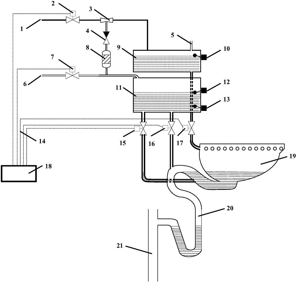
[0012] The present invention will be further described below in conjunction with the accompanying drawings. Such as figure 1 As shown, a toilet flushing system with a jet pump, including a flushing water system and a water-saving system;

[0013] The flushing water system includes a tap water inlet pipe 1, a tap water control solenoid valve 2, a jet pump 3, an air vent 5, a tap water storage tank 9, a liquid level detection float switch 10 and a flushing water control solenoid valve 17. The tap water inlet The pipe 1 is connected to the tap water storage tank 9 through the tap water control solenoid valve 2 and the jet pump 3, the outlet of the tap water storage tank 9 is connected to the toilet through the flushing water control solenoid valve 17, and the toilet is connected to the sewage main 21 through the sewage piping system 20 The tap water control solenoid valve 2 and the flushing water control solenoid valve 17 are respectively connected with the solenoid valve group ...


PUM


Abstract

The invention discloses a toilet flushing system with an injection pump. The toilet flushing system comprises a flushing water system and a water saving system, wherein the flushing water system comprises a tap water control solenoid valve, the injection pump, a liquid level measurement float switch and a flushing water control solenoid valve, and the water saving system comprises the injection pump, an air control solenoid valve, a high-liquid-level measurement float switch, a low-liquid-level measurement float switch, a water sucking control solenoid valve and a siphon water release control solenoid valve. According to the toilet flushing system, the injection pump is added, so that part of pressure energy of the tap water is recycled, and the part of energy is used for recycling part of water for urine flushing of the toilet; during the faces flushing, the recycled water is drained into a drain pipeline of the toilet earlier than the flushing water of the toilet, siphon force is generated for sucking dirt such as feces, and then the water with the amount being equal to that of the water used for flushing urine is released for flushing the toilet to be clean. Compared with the existing water-saving toilet, the toilet flushing system provided by the invention has the advantage that the amount of the water for flushing the feces is reduced by one half.

Description

technical field [0001] The invention belongs to the technical field of water saving, in particular to a toilet flushing system. Background technique [0002] In order to achieve the water-saving purpose of the toilet, people have made a lot of improvements to the existing toilet flushing system, such as: improving the linearity of the water flow in the design of the toilet to generate a swirl; changing the internal structure of the toilet flushing water flow , change the outlet position of the flushing water; change the structure of the toilet's sewer channel; improve the state of the inner wall of the toilet, etc., but when defecating, because there are more dirt and solids, it must rely on a large amount of water to wash away, and at the same time Relying on the siphon force generated by the flushing water flow to discharge sewage makes the flushing water volume of stool much larger than that of urinating, and it cannot be reduced, which has become a bottleneck for toilet ...

Claims


Application Information

Patent Timeline
Patent Type & Authority Applications(China)
IPC IPC(8): E03D5/01E03D9/16
CPCE03D5/01E03D9/16
Inventor 李策略董景明严志军宋赫陈旭立潘新祥
Owner DALIAN MARITIME UNIVERSITY
Why Eureka
Try Eureka